Summer 2026 Internship
After graduating in May, I decided to pursue another internship before beginning my master’s degree program. I traveled just an hour south of Purdue to work at a welding robotics company in Indianapolis.
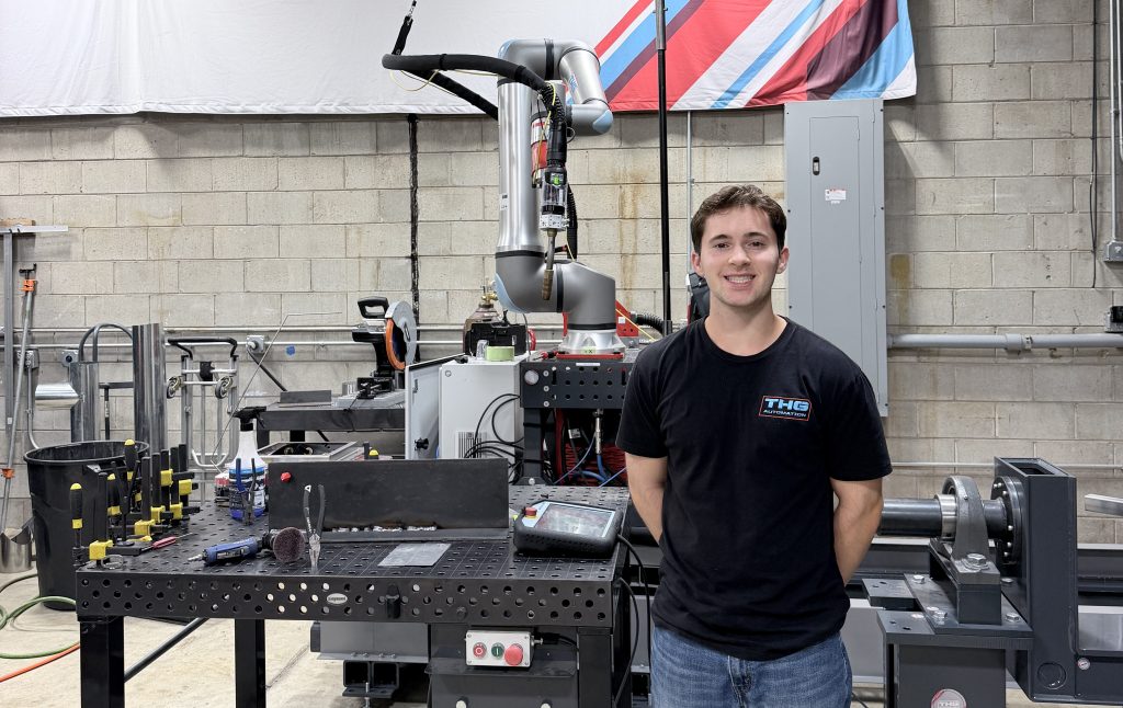
This company is unique in the automated welding industry as they use industrial cobots instead of traditional robots. They are easier to program and require fewer physical safety barriers for workers (I will use the word cobot and robot interchangeably throughout this page though).
Despite working there for only 11 weeks, I was able to make significant contributions to several projects. This page highlights 3 major projects and a few side ones I did for fun. Although it is by far the longest and most detailed writeup on my website (~5500 words), I did have to leave out a fair amount of detail and design decisions so I could actually write about each project in a reasonable amount of time.
Project 1: Robotic Linear Rail Integration Weldments
My first project was creating custom support fixtures for a large HVAC equipment company. This project lasted the full length of my internship and is still in progress as of writing this (August 2026), but I will update with more photos and videos after it concludes.
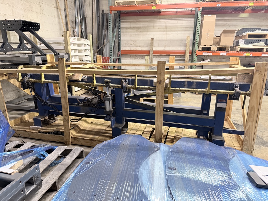
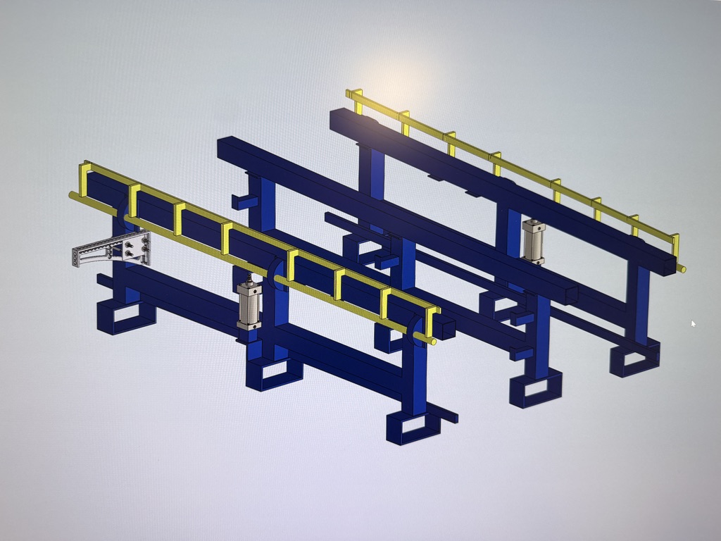
The company builds a type of large metal air vents and uses these blue fixtures to hold their parts in place as several workers manually weld them all together. They wanted a fully automated solution using several robots instead. My task was to create custom parts that allowed our robotic linear rails to connect to the customer’s existing fixtures (an integration project).
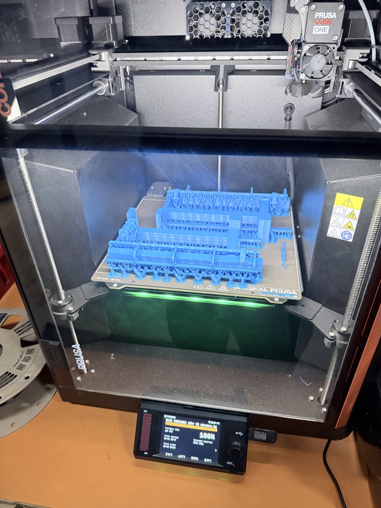
To accomplish this, I reverse-engineered a set of their blue fixtures that were shipped to us. Using a tape measure and dial caliper, I recreated these parts with functional pneumatic yellow clamps (see photos above) inside SolidWorks. Once the blue fixture models were done, I began the tedious and iterative process of designing weldments to connect our rails to the customer parts. In this context, weldments describe the parts I made consisting of several steel plates welded together.
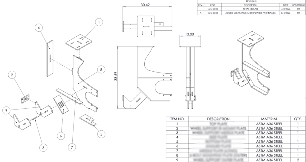
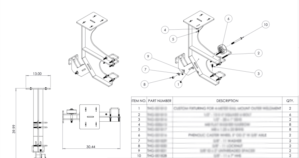
The design we eventually landed on used 9 separate ½” steel plates that all fit together using a tab-and-slot design, sort of an “I-Beam” concept if you will. By using a collection of plates, all of the parts could easily, affordably, and quickly (1-2 weeks) be waterjet cut by a local company. The weird shape comes from attempting to create a universal design that could mount in multiple places on the customer’s fixture. Using u-bolts, the weldments attached securely onto the three vertical posts on their fixtures. A large caster wheel was added in the back to support the weldments and assist with moving the whole setup.
When designing these weldments, I used the model I created of the customer fixtures to trace out the pneumatic clamp’s path. Using the motion study feature in SolidWorks, I projected this path onto the part. It worked well; the video below (from later in the summer after everything had been built) shows the clamp moving with a consistent ~1.5″ gap from the parts I designed.
After modeling all of the parts and before they were physically ordered, I 3D-printed the separate components at a small scale (complete with mini u-bolts) as a proof-of-concept and to see how it would all fit together.
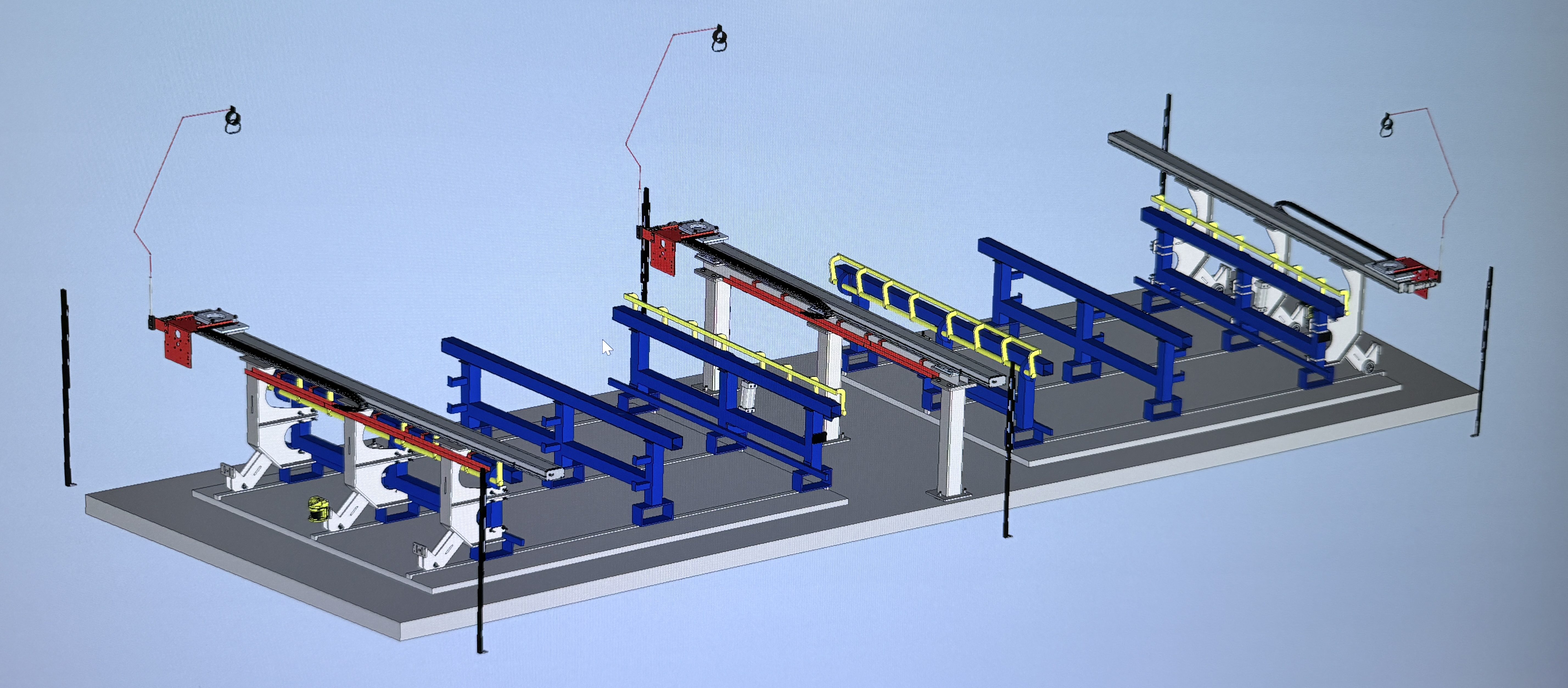
I started 3D-printing a lot during this project, and it quickly became a bit of a passion of mine. Later on this page, I included all of the other things I printed. However, I think it’s important to note the customer really enjoyed seeing this print as it increased their confidence in our ability and dedication to this project.
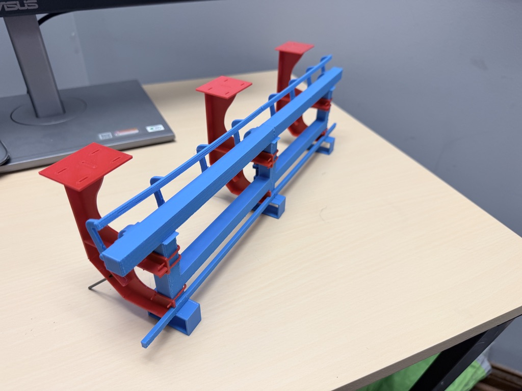
Once the waterjet parts arrived later in the summer, it was really cool seeing the full-size metal next to the small 3D models.
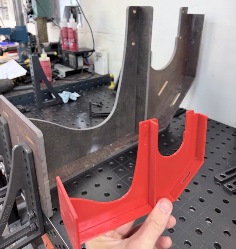
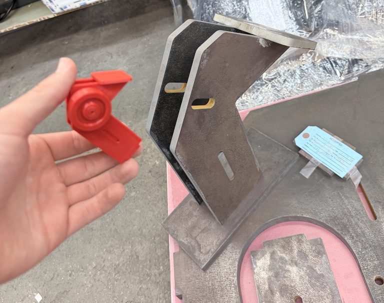
In addition to these side-mounting weldments, I also created a floor-mount design to sit in between two sets of the blue customer fixtures and to hold an additional UR robot and linear rail.
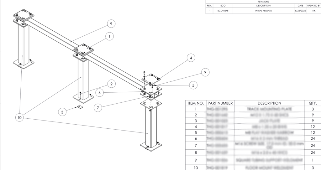
These floor mounts had an interesting multi-plate design that rested on one large cross-member and 3 smaller steel tubes. We built it this way to make shipping and on-site assembly of the weldments easier for our production workers. All three of the pedestals for this floor-mount have slotted plates to help with manufacturing variance and jack plates to help square everything up.
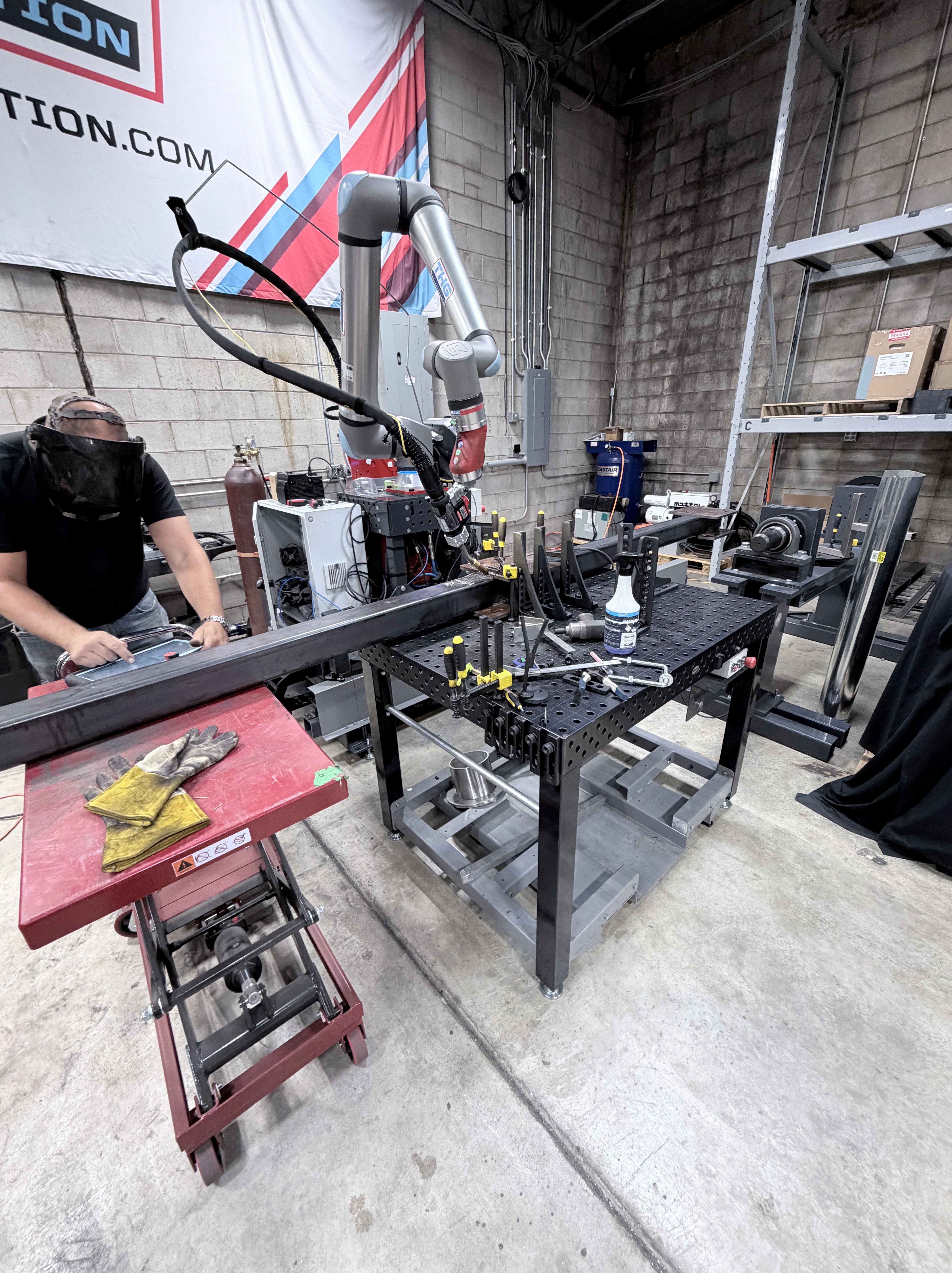
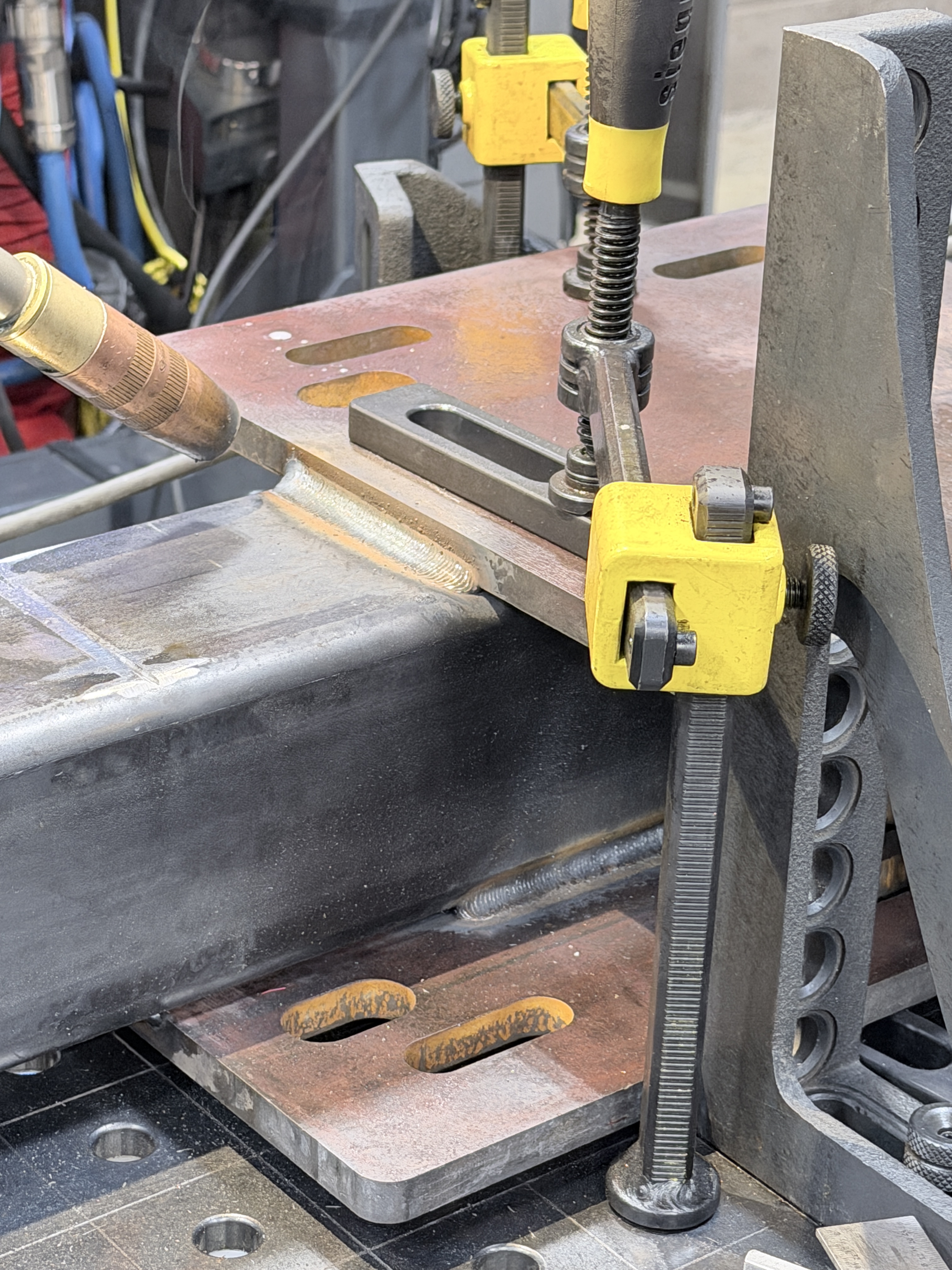
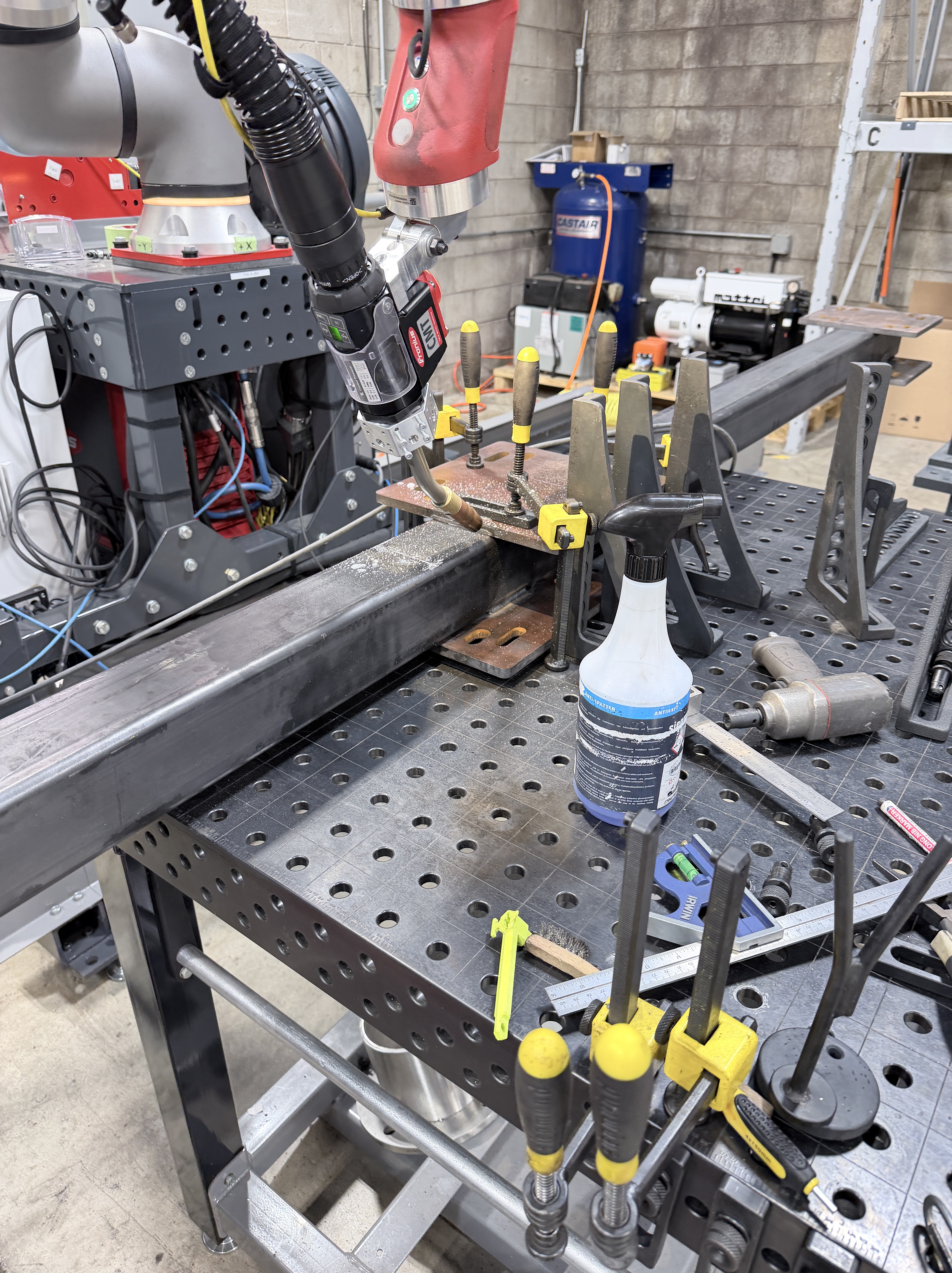
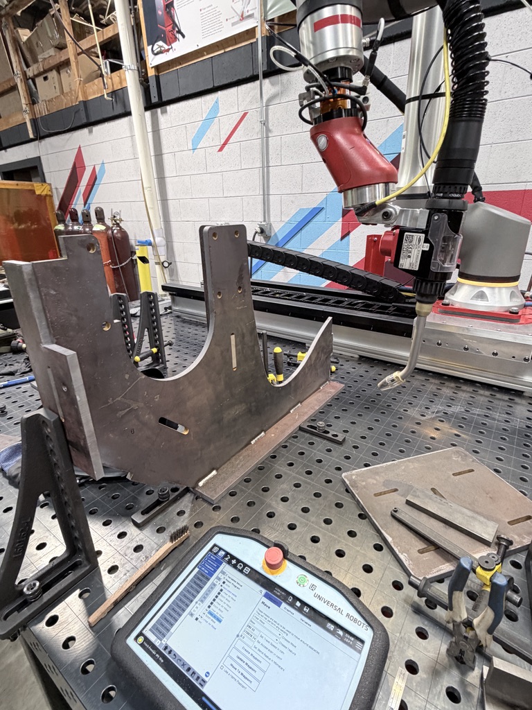
The ½” steel plates were all welded together robotically because multiple sets were created for the customer. The final design consists of 12 side-mount weldments and two full floor-mounts so manual welding would be less efficient. The following video shows an example of one of our robot systems in simulation mode (movements but no welding), programmed to tack weld one side-mount weldment together.
After the parts were all welded together, they were painted in-house and the assembly process began. Although the final order requires many more weldments, we initially only ordered one set (3 side-mounts, 1 floor mount) for a part run-off. The customer requested this so they could make sure everything worked before final installation in their facility.
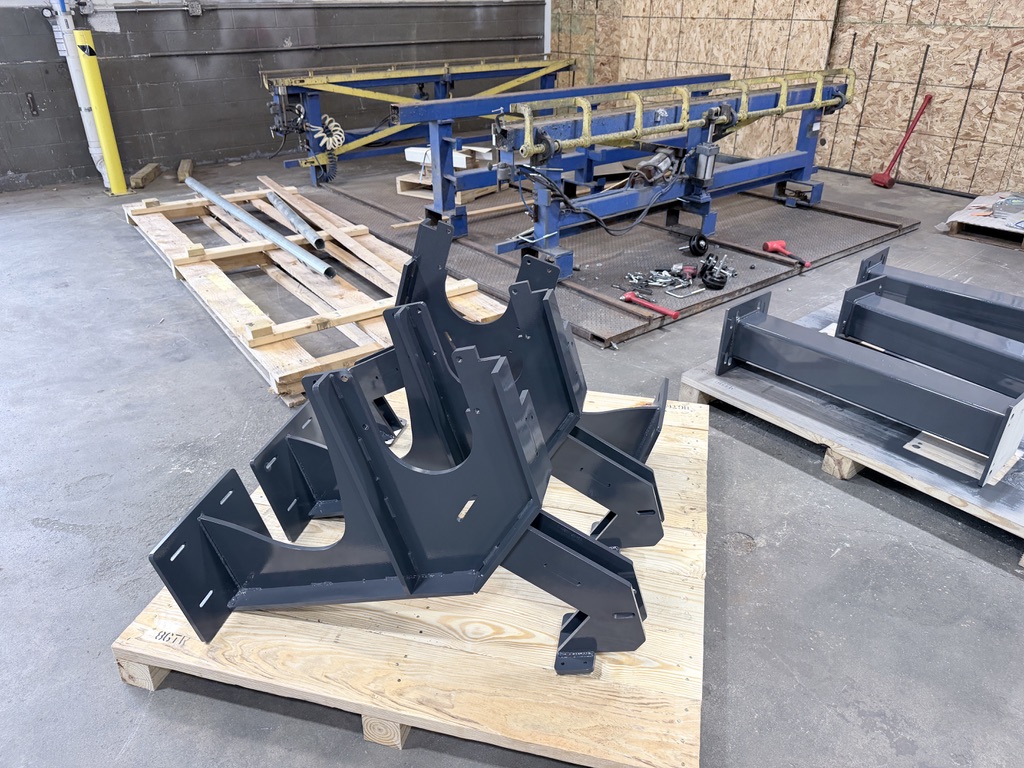
Although this first set of parts was usable for the runoff, there were several small issues (as there always are and will be for integration projects like this). Although I am a little biased towards my own work, most of these issues truly did stem from the design of the customer fixture. They were originally created in the early 2000s (4 years before I was born) and not intended for welding automation. Years of heat soaking from welding left them warped and with many defects. In the beginning of the project, I did not account for this, and so the virtual models I created of their fixtures were perfectly straight.
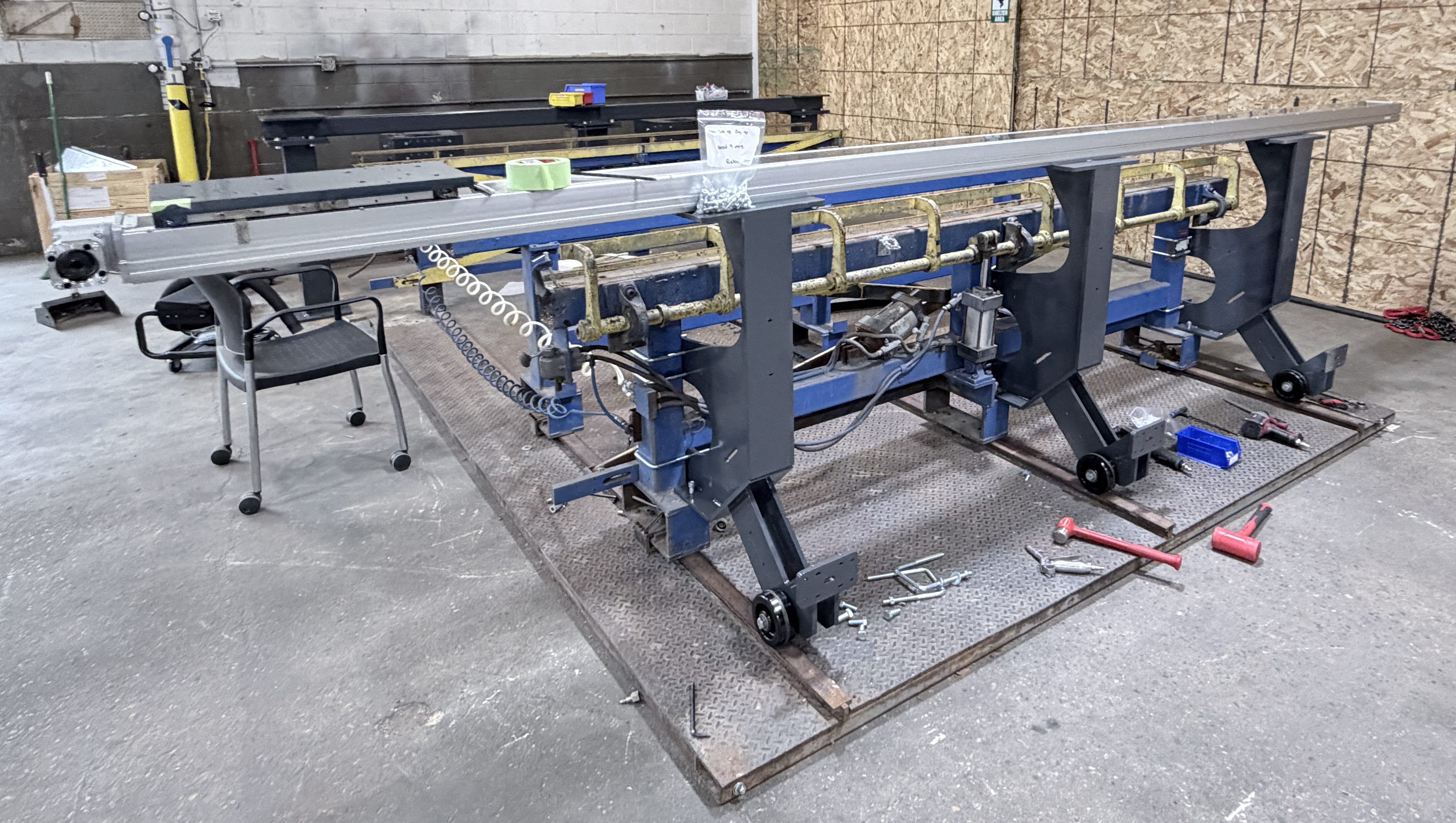
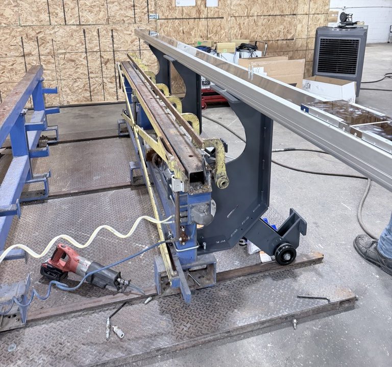
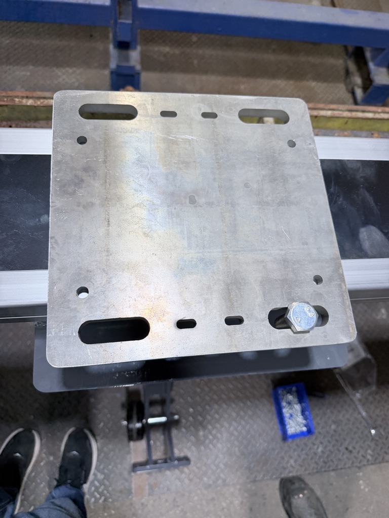
This meant that the holes for the u-bolts were not large enough for areas on the post that had expanded or were covered in weld spatter, and the holes to hold the large steel rail on top did not line up in a straight line. Also, the front edge of the weldments rubbed against an inner yellow x-bar support I didn’t think to include in the 3D models. All of these problems combined to make assembly a bit of a challenge (see photo below).
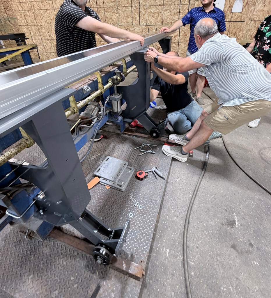
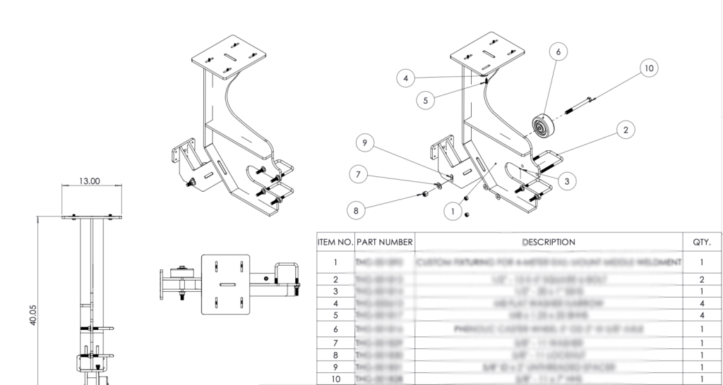
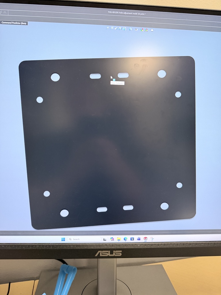
To account for these issues, I slightly redesigned the weldments before we ordered the rest of the set. I created a special “middle side-weldment” to fit the center post so it wouldn’t contact that yellow x-bar. I also increased the u-bolt hole size on each plate to make assembly easier.
For the top plate holes, I 3D-printed a template part that could be easily used to drill new holes in the correct position for each post.
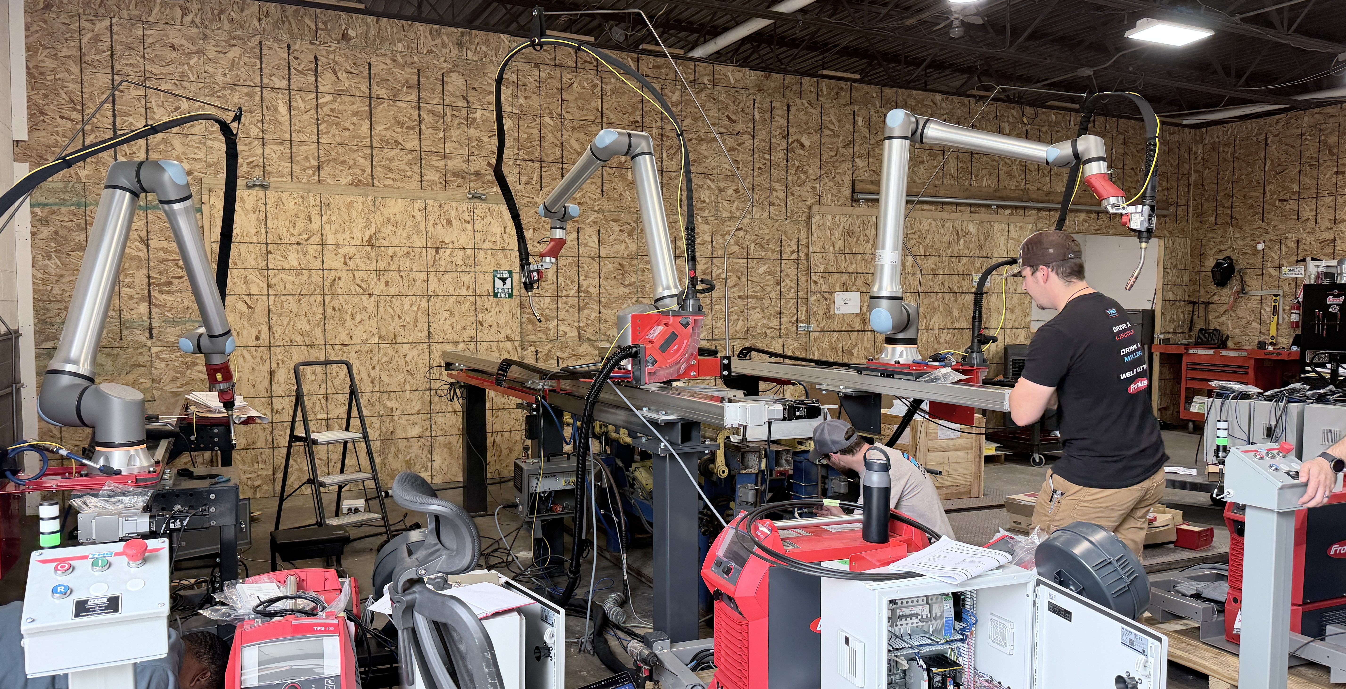
Besides the weldments, there were several other small issues we ran into throughout the assembly process that all required quick fixes.
For example, the cable chain (a bracket that holds wires in place as the robot arm travels down the rail) sat about an inch too high above the mounting bracket. This caused it to fall and get caught on other components. To fix this, I 3D-printed this support bracket.
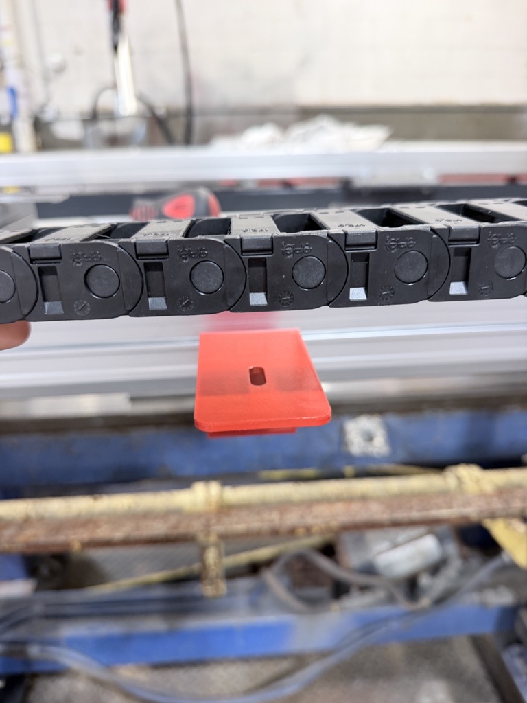
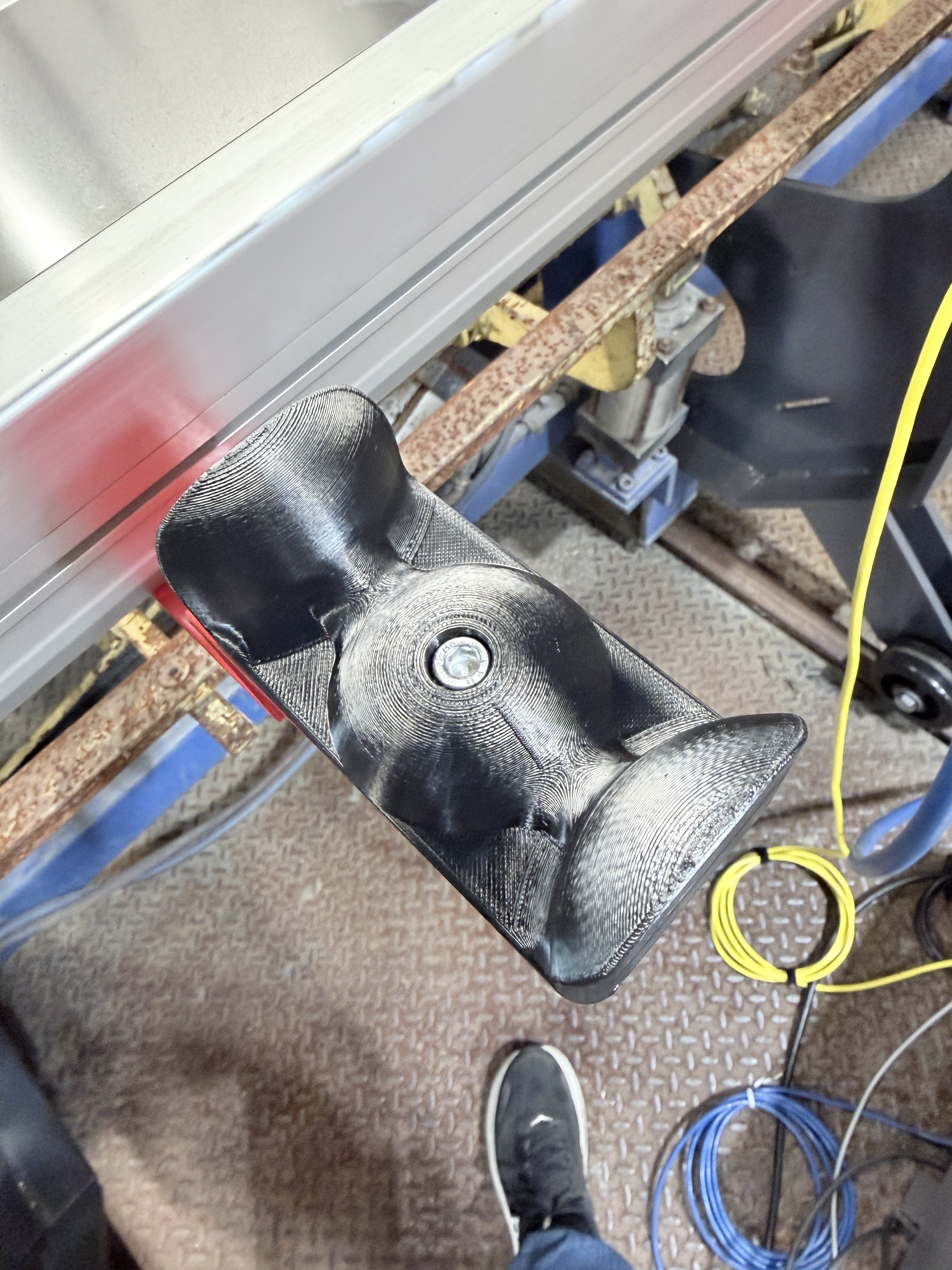
The curves on the bracket guide the chain straight and keep it supported as the robot moves. It also has a counterbored hole to keep the screw out of the way of the wires.
The project was still in the assembly phase when I completed my internship, but it should be shipped to the customer within the next few months.
Project 2: Custom Welding Fixtures
The second main project I worked on was creating a set of 3 custom welding fixtures for an industrial scissor lift company (lifts used to raise heavy vehicles like trucks and buses). Designing these parts proved to be quite a challenge and I learned so much doing it.
Really, the difficulty lay in the engineering requirements for the design. The company had 3 parts they wanted to be welded fully automatically. We had quoted a large dual-axis positioner to hold their parts but needed to design fixtures to keep them constrained for the actual welding. The fixtures would need to easily attach to the positioner, constrain the customer parts in all axes and locate with several datums to ensure accurate positioning for the weld programming. Also, the parts weighed ~300-400 pounds, were designed in 2010 (I was 6 years old), had some specific large tolerances, and would likely be held completely upside down at various points in the welding process (sounds easy enough).
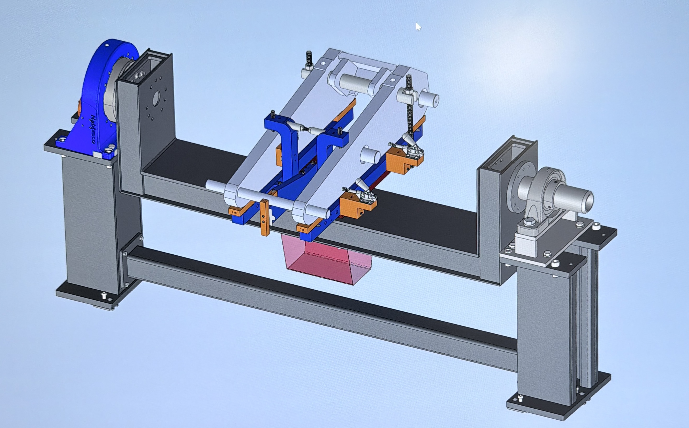
We decided on a modular system that utilizes many mechanical fixturing concepts to hold the parts in place. After a frustrating but necessary amount of iteration, I created the following system.
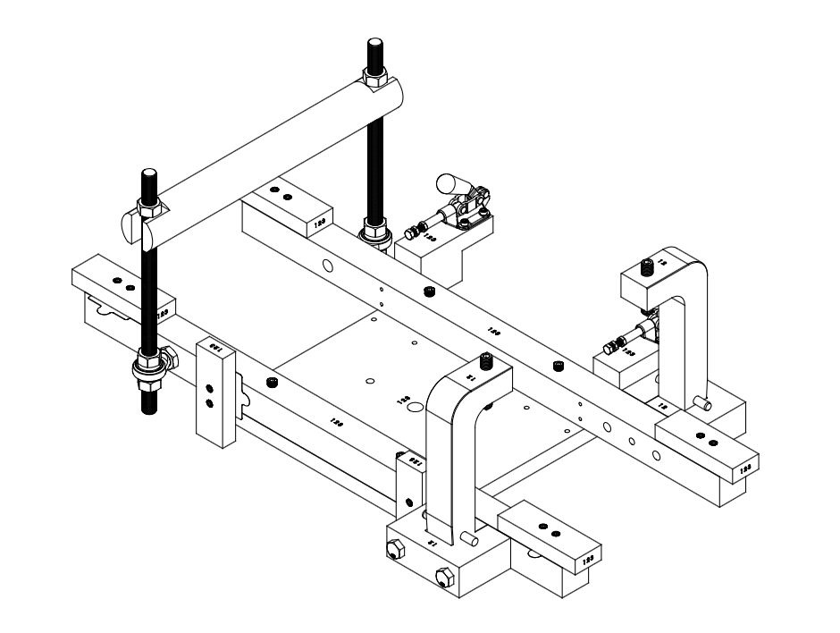
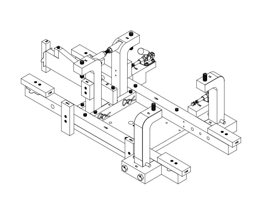
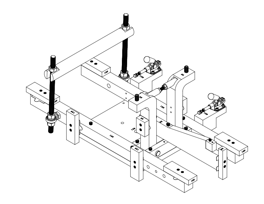
Each of the customer’s parts has its own dedicated fixture, but they reuse many of the same parts and concepts. All three have the same base plate, side support bars, shimmable support wear blocks (custom steel shims were designed to be waterjet cut), and toggle clamps to push the parts into place. The support wear blocks were positioned to rest only on machined surfaces and the toggle clamps were implemented to mirror the customer’s existing fixtures for manual welding. Each support arm also has a large cone-tip set screw to securely hold the parts each at a single point.
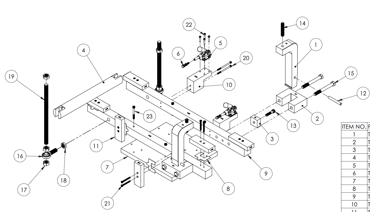
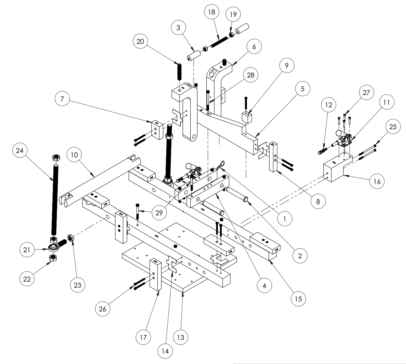
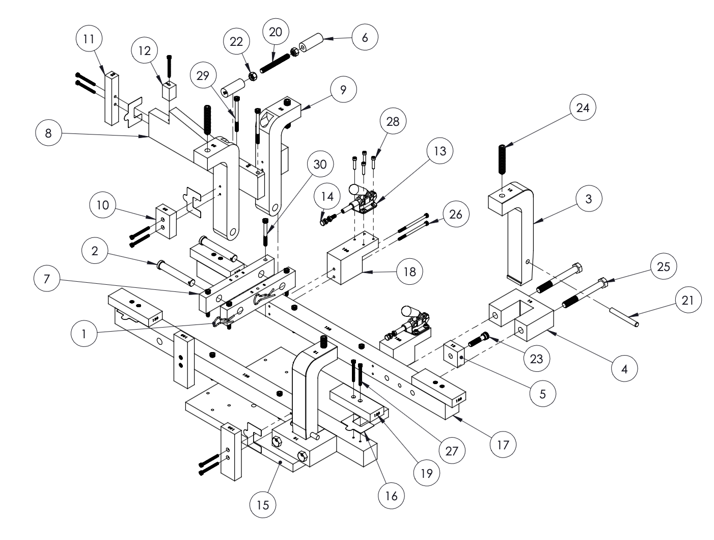
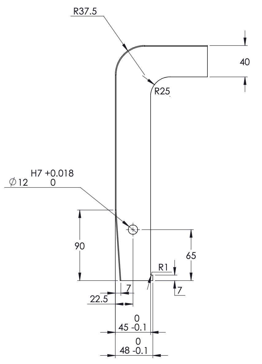
The parts were located in a variety of ways, such as a steel bar that fit into a hole on the part and was machined to hold a threaded steel rod on either side. There was also a front block that located a fixed rod in the customer parts. To hold the parts when the whole assembly was turned upside down, I created clamp arms that could hold from both the inside and the outside of the part. The inner clamps are held by clevis pins so they can easily rotate and additional surface wear blocks to keep the parts from warping inwards during welding. The outer clamp bars utilize a slightly different concept (see drawings below). Instead of rotating, they act as both a mechanical wedge and have a small foot on the bottom. The clamps have an angled chamfer on the side so that they must be put in at an angle, and then, when the top set screw is tightened, the foot pulls up into the mounting block and holds everything securely in place.
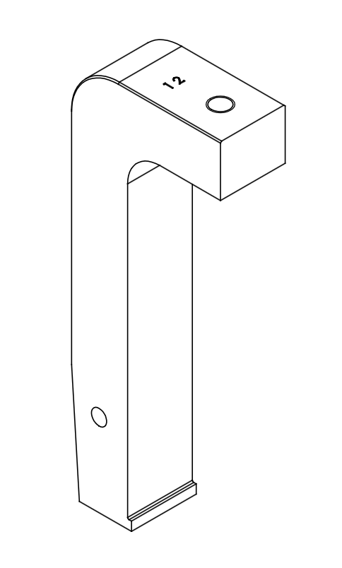
As you could imagine, the large number of components and hardware for these fixtures led to some very interesting but complicated assembly drawings. Although a bit too confusing for assembly purposes, I created these exploded views to diagram and better identify all of the parts for each fixture. To further reduce costs, these fixtures reuse a lot of the same screws throughout and several that previously existed in the company database. The modular design also allows individual parts to be redesigned or updated in the future if any one of them does not work well enough. Additionally, each part is stamped with a number or multiple (1, 2, 3) to signify which customer parts they will be used on. The numbers are all positioned to face towards the center of the plate to implicitly show their correct orientation.
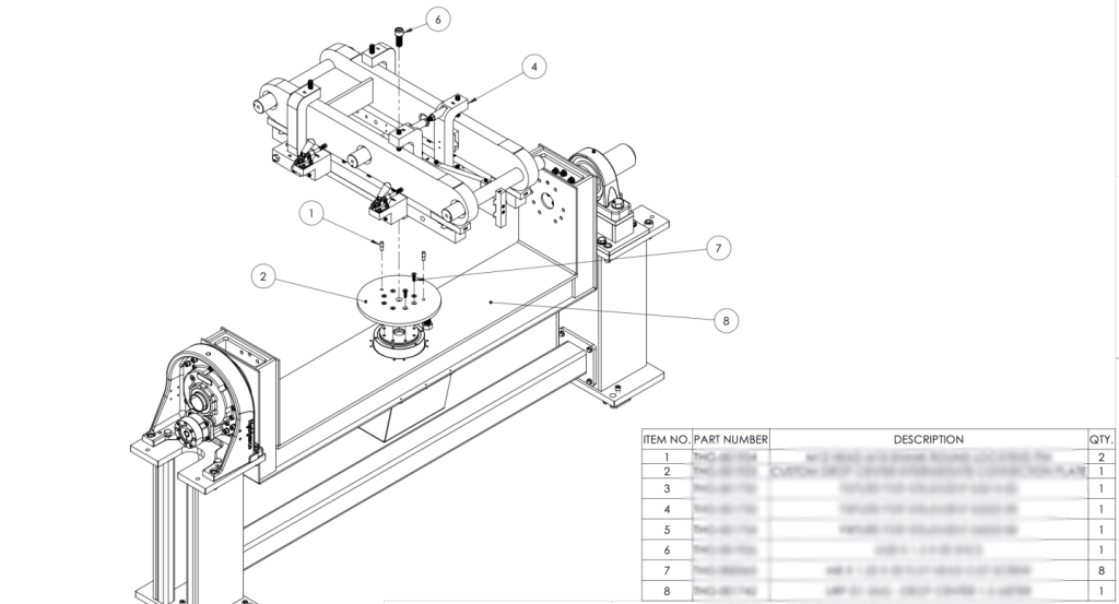
Attaching these fixtures to the rotating positioner also created an engineering challenge. At 4pm on the Friday of my second to last week of interning, I spoke briefly with the engineer in charge of this project at the customer’s company. In contrast to the original design I had that required 8 bolts to be removed each time, he introduced a new requirement that they would like to be able to switch between each part quickly and effectively so a set of three could be welded in series. To accomplish this, we created an intermediate attachment plate to sit between the positioner and the fixtures (see assembly diagram above and part drawing below). It stays permanently attached to the positioner with 8 countersunk bolts and then locates each fixture with two round-head pins and one large bolt.
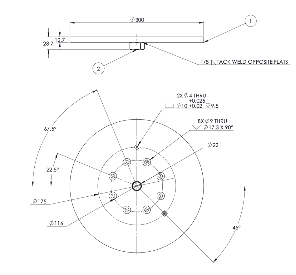
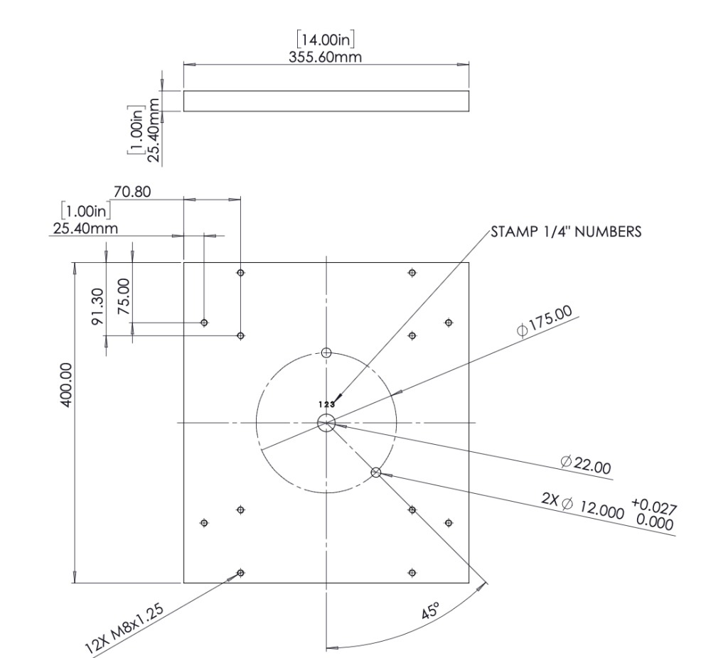
These drawings show how the pins were positioned to prevent incorrect assembly. The base plate (below) has two holes for the pins to sit in that match the intermediate plate’s design. Precise tolerances were used on each drawing to ensure the correct fit (interference, clearance, etc.). An M20 nut was tacked to the base of the plate to hold the large bolt in place. A nut was used instead of threading the hole because the threads will likely be worn down quickly since the bolt must be removed every time to switch fixtures. A new nut can be tacked on much easier than making a whole new plate.
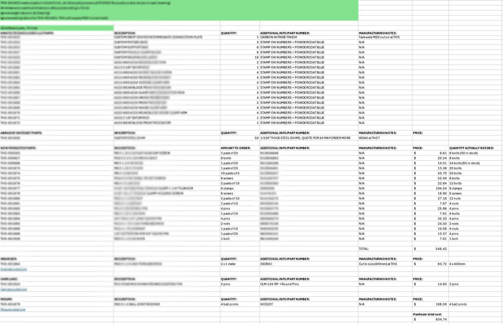
I’m very proud of how it turned out given the complexity of everything, but unfortunately my internship ended before we could have all of the parts ordered and machined. To make this process as easy as possible for after I was gone, I created a spreadsheet highlighting exactly what parts needed to be ordered, quantities of each, and created a zip file containing all of the necessary drawings, DXF files, and 3D STEP models. This spreadsheet also outlined the exact amount of hardware that needed to be ordered, including pack sizes from McMaster-Carr and a few other distributors to save over $400.
Since I knew I wouldn’t get to see the final product in person, I 3D-printed a functional magnetic dual-axis positioner, the fixtures I designed, and the customer’s parts at a 1/10th scale. The magnets allow the fixtures to be easily removed and attached, simulating what the actual parts will do. A video of this 3D model can be seen later on the page. I color-coded the digital CAD model to assist in development but the real parts will all be painted blue as per the customer’s request.
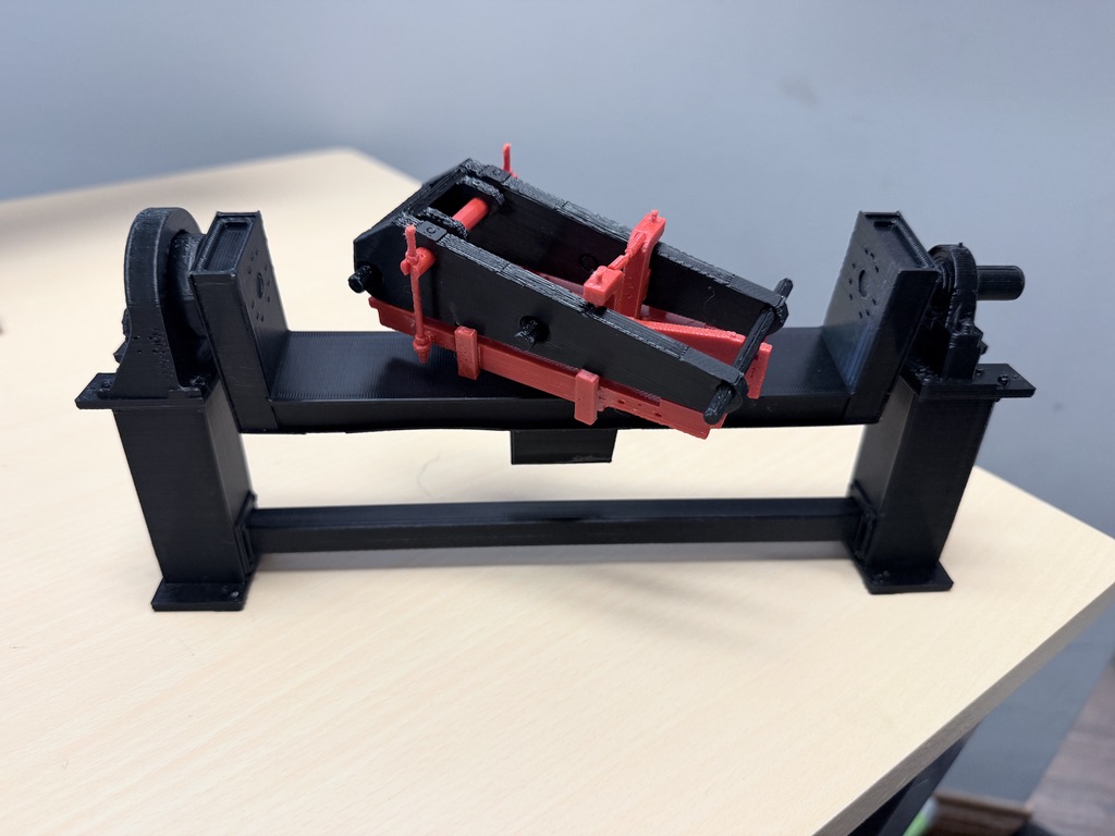
As of writing this (August 2026), this project is still in development by the company, but I will add additional photos/videos after it has concluded.
Project 3: Tool Balancer Rod
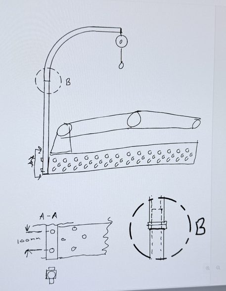
My favorite project I worked on this summer was this “Tool Balancer Rod” design. This was created to solve an interesting and very specific problem. Traditional industrial welding robots incorporate the welding hose (the hose that holds the wire and carries gas to the torch) directly into the robot linkages. For cobots, however, the hose sits outside the robot and thus must be secured in some way. It can be strapped directly onto the robot but this may cause issues when the cable needs to stretch for certain positions. Also, since the company sells systems where the torch toolhead is automatically changed for a different type of welding (MIG or TIG), the hose needs to stay separate from the robot.
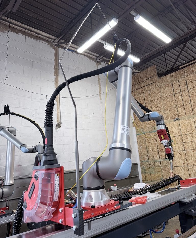
The company’s original solution to this problem was a large metal rod bent specially to hold the hosepack in tension while the cobot moves the torch around. Although effective in many cases, it can easily tangle on the robot linkages and prevents many specific welding positions. SpaceX, one of the company’s biggest customers, really did not like the existing solution (they often removed it entirely to just let the hose dangle) and wanted us to come up with something better.
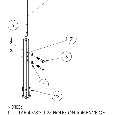
After overhearing this conversation, I volunteered to work on making it happen (it sounded fun). The owner of the company had a few ideas using EMT conduit, a type of cheap round metal tubing used to hold electrical wires. The overall concept was to use a retracting tool balancer to keep the cable out of the way, wheels to let the tool balancer roll, and a dowel pin for a bar to rotate on. Using those ideas, I created the following after a few iterations. EMT conduit is bent at a 90 degree angle to create an L-shaped arm. The upper arm rotates on a dowel pin while the lower half stays fixed and a tool balancer rolls along a straight section using custom designed wheels.
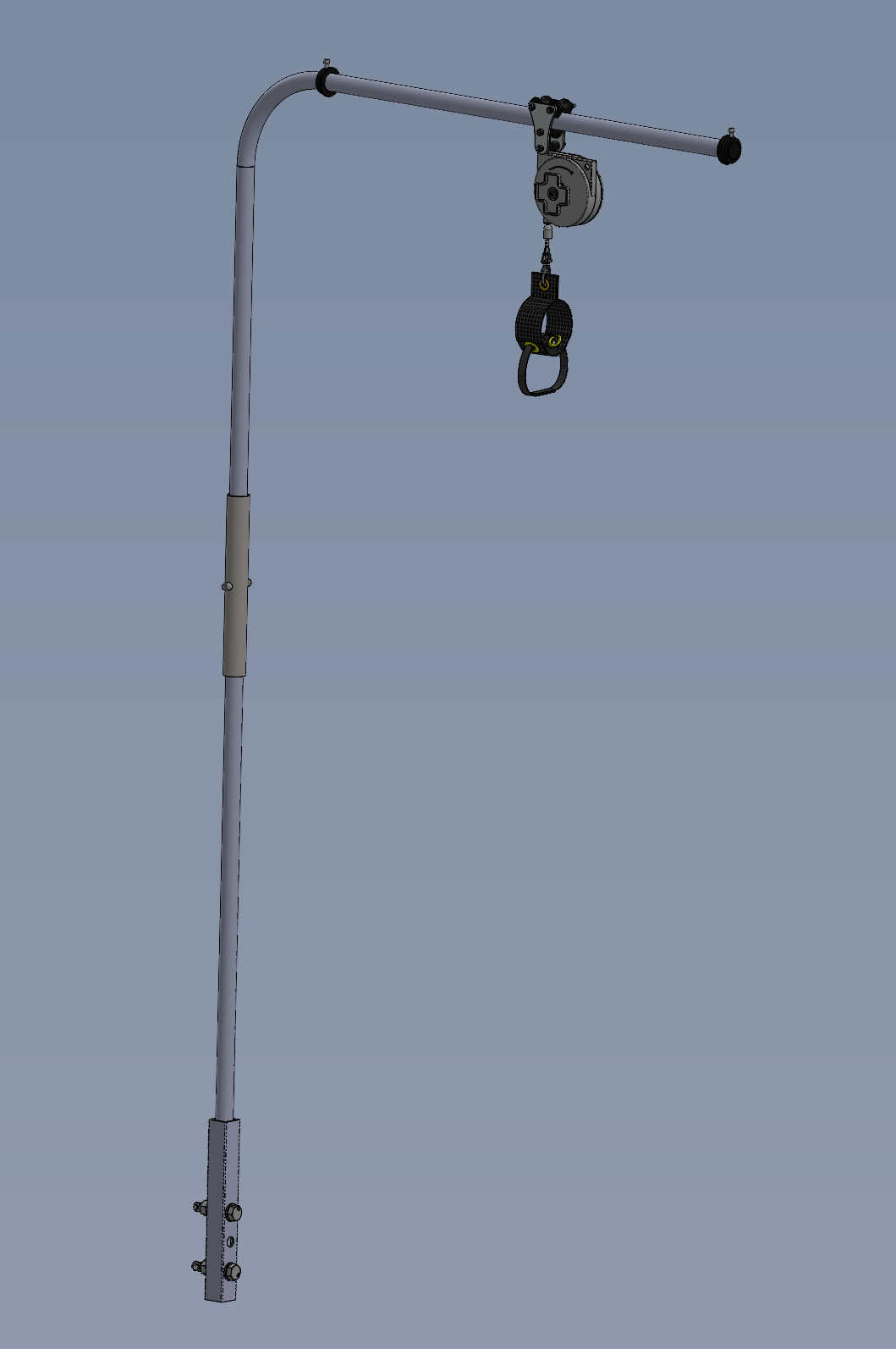
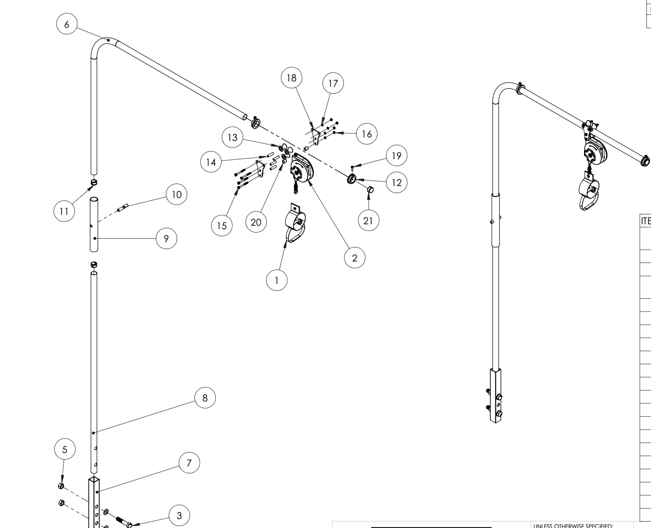
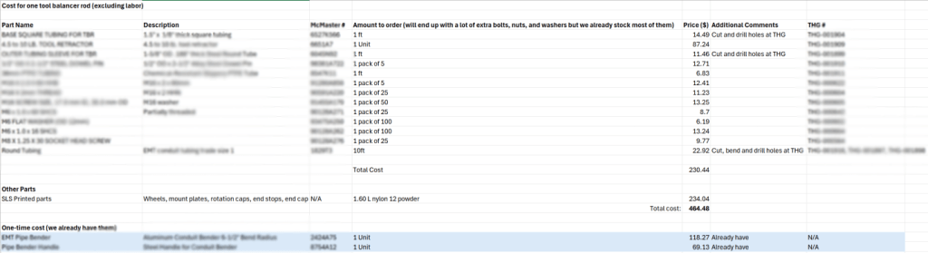
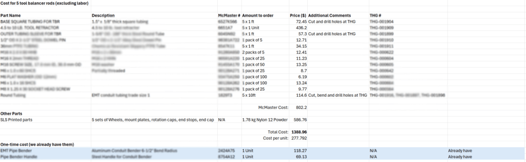
Building this design was really interesting and I used a couple of methods to make it easier. All of the nuts and bolts were parts already stocked for other projects, and every other non-custom 3D-printed part is easily and affordably found on McMaster-Carr. After reviewing the model, I created a spreadsheet outlining all of the parts and ordered them.
I got to machine all of the conduit tubing and other components myself with a drill press. I also bent the tubing with a manual foot-bender (had some help from another employee to do this).
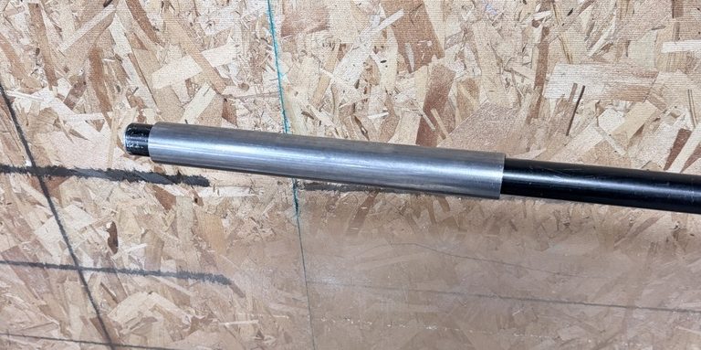
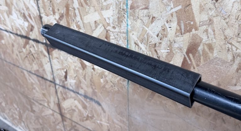
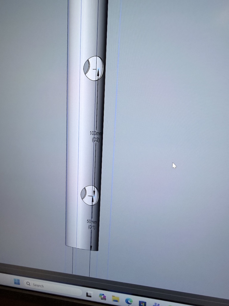
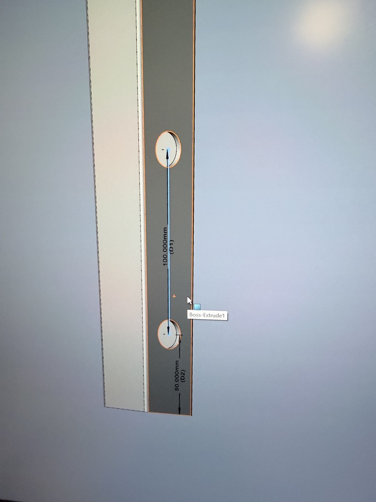
Designing the wheel subassembly was the best part of this project, but it required a lot of iteration (see below). Besides the wheels, I also 3D-printed custom mounting plates, and rotation caps to make everything rotate easier on the dowel pin.
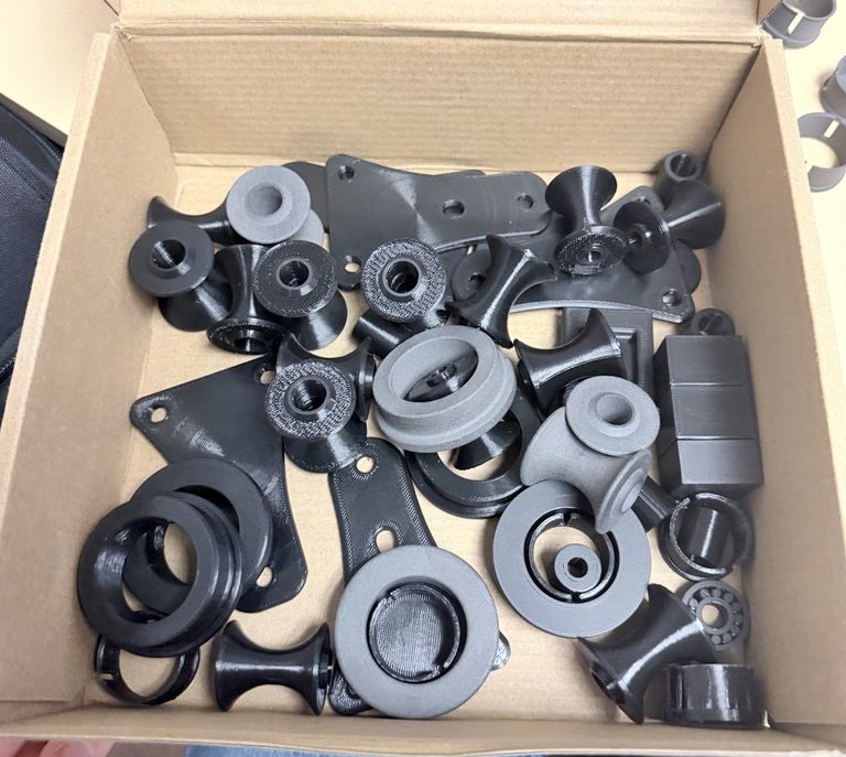
The wheels have essentially a “yo-yo” shape, allowing them to roll easily on the conduit and also rotate around it sideways to ensure a smooth movement. Inside of each wheel is a large shaft hole to fit PTFE tubing. The tubing is important because it allows the mount plates to be tightly secured with a nut but let the wheels still roll freely. The wheels were redesigned a few times because initially they merely slipped across the conduit tubing instead of actually rolling. Although this slipping did work in practice, it would likely cause the parts to wear down and fail sooner. To fix this, I simply reduced the outer radius to force more surface area to be in contact with the tubing.
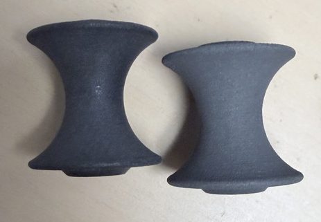

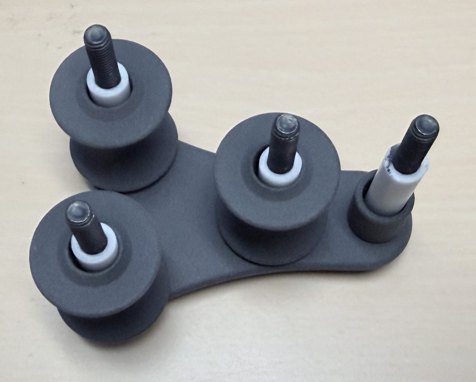
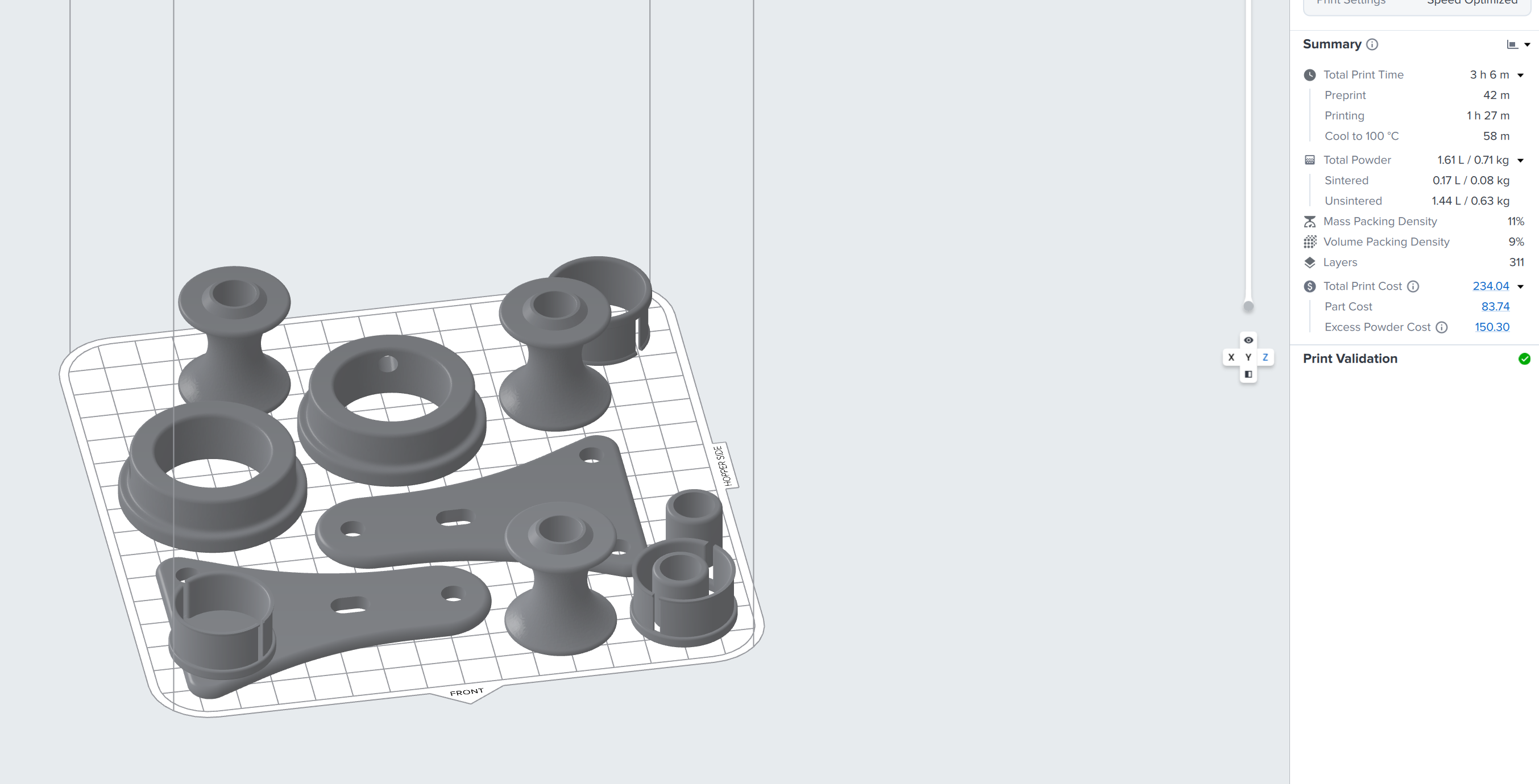
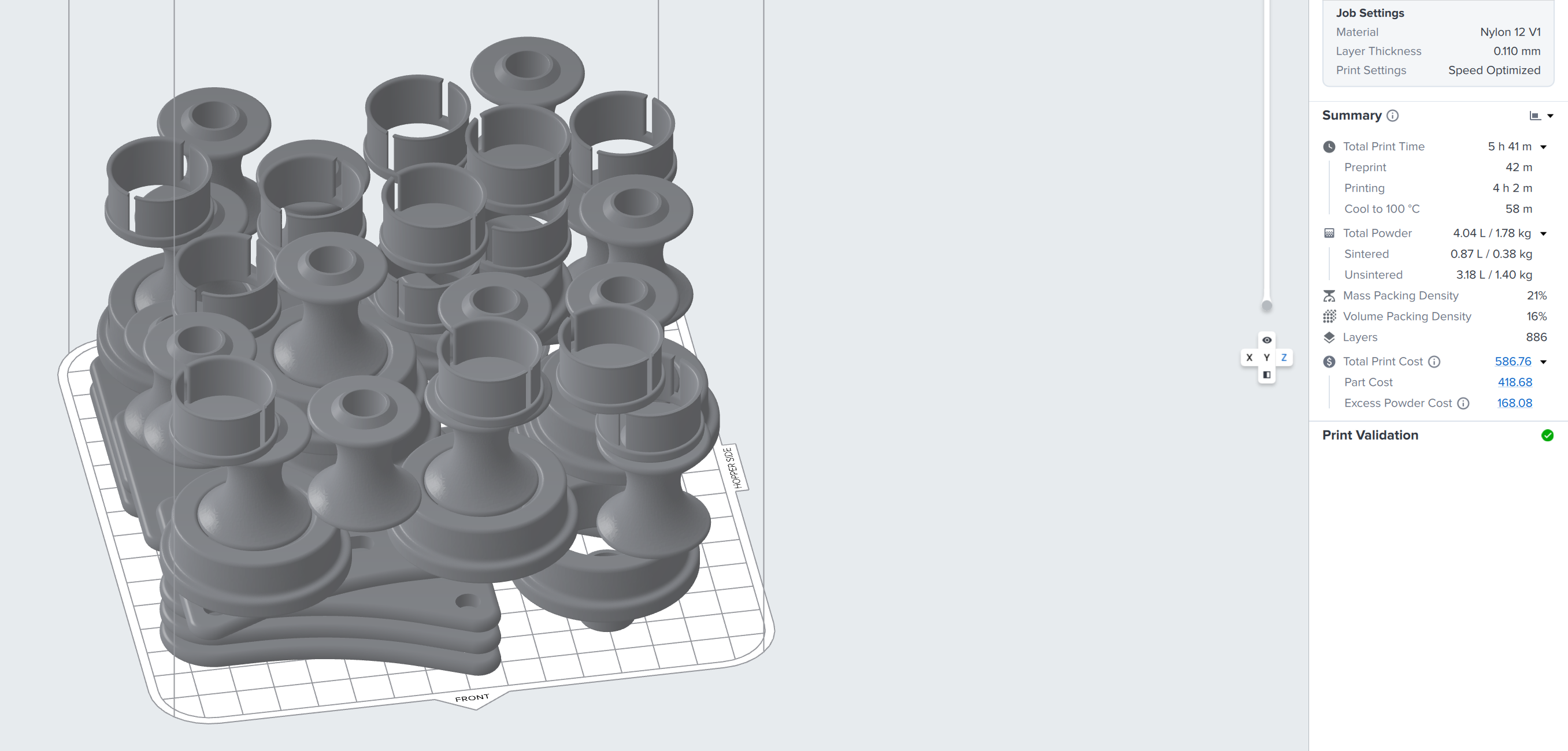
After 3D-printing and some proof-of-concept testing, I SLS printed the parts in nylon powder. Although a little more time-consuming (and much more expensive than PETG filament), the SLS parts are far more wear resistant and smooth.
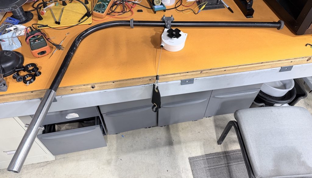
The SLS printed end-stops are cool in that they can be adjusted to find the optimal linear travel distance for the wheel sub-assembly. After a bit of trial and error, I was able to find the correct diameter so that an M6 screw can self-tap into the side hole, further reducing assembly complexity.
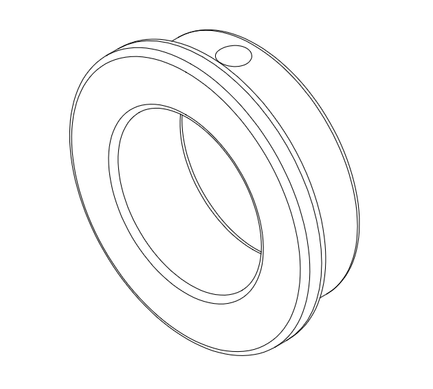
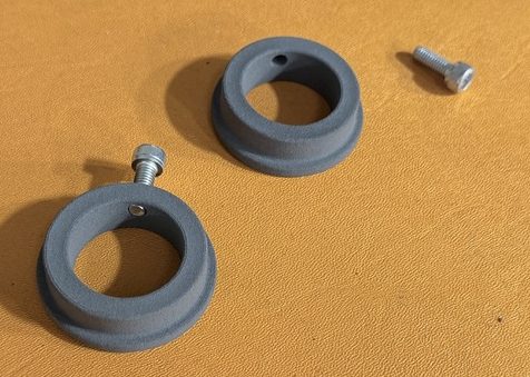
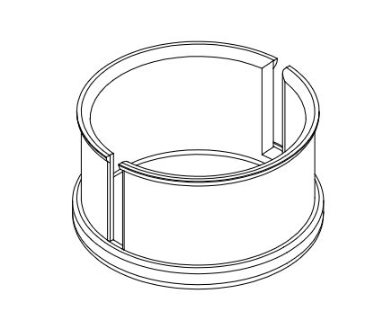
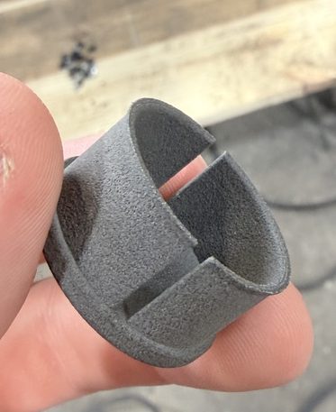
I’m also a big fan of these custom rotation caps I made to rotate on the dowel pin. I’m curious to see how they wear over time, but thankfully even if they slowly crumble, the conduit rotates well enough with metal on metal contact. I modeled them after some similar caps I saw online but with a custom size for this conduit tubing. The thin walls allow them to bend and fit inside the tubes and then hold themselves in place.
I have included several demo videos in this section too, but please first watch the following stop-motion assembly to get a better idea of how it all fits together.
Here are two videos showing the TBR in action. The first is manually moving the torch head on a UR20 setup and the second shows a short testing program running on a loop on a UR8 cobot. The UR8 setup is also the same one used in the first project on this page but I just switched the old steel rod design for my prototype for some brief testing.
The prototype ended up working far better than I expected! It held the hosepack out of the way of the robot very well, allowing for many welding positions that were impossible with the old design. Although not perfect for every situation, it was a major step forward and a big improvement. One issue that was also present with the old design is that the robot can collide with the vertical rod if it moves too far back. To combat this, I also designed a longer version of the TBR that mounts at the base of the UR robot support pedestal. Here is a drawing and 3D model of that, I was not able to actually try it out before my internship ended. The design uses essentially all of the same parts, besides a longer horizontal straight section to ensure the same reach is possible.
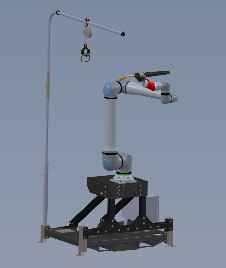
Overall, I was very proud of this project as it only took about two weeks and mostly solved an annoying issue that had persisted for over 4 years. Although quite large, it is relatively simple and cheap (ish) to produce.
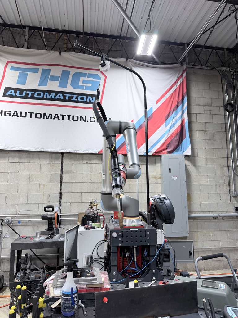
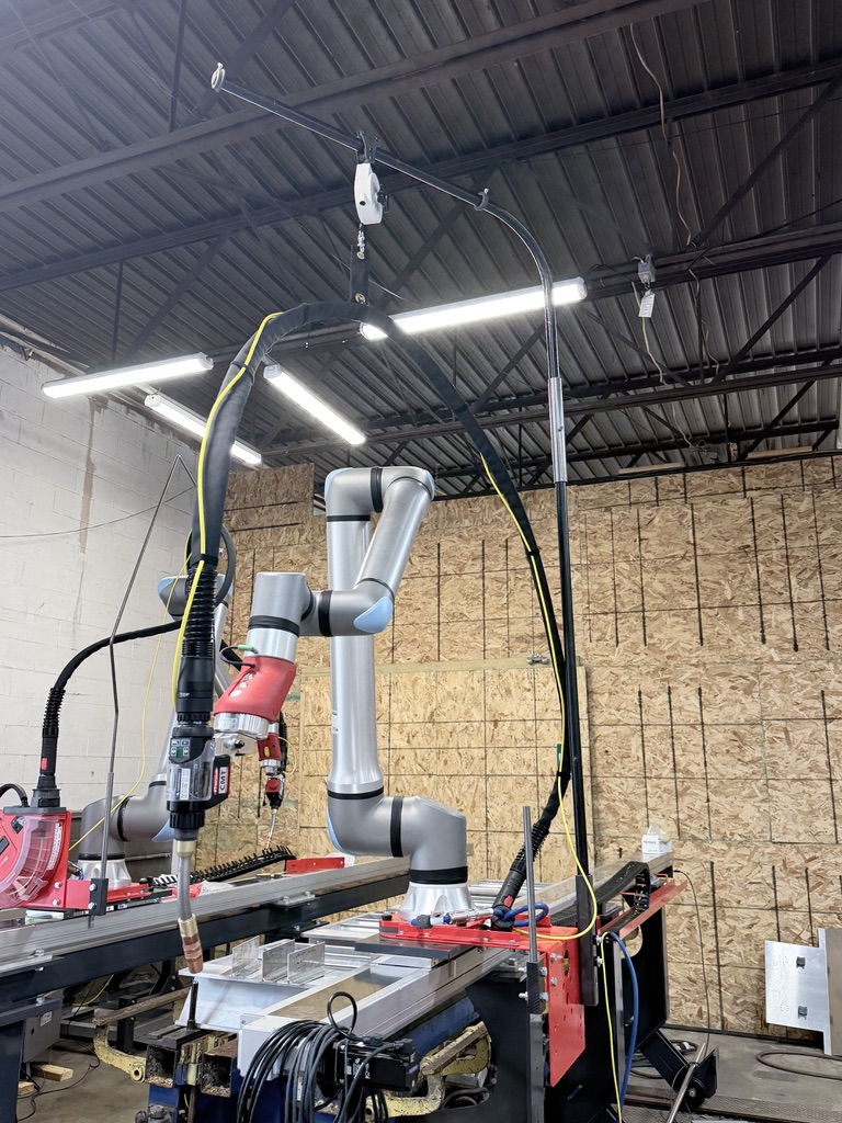
To help reduce costs and make producing it more realistic, I created files to SLS print 5 sets of parts instead of 1 and a spreadsheet with all of the things to order to create 5 whole assemblies. Due to hardware pack size, and the nature of SLS powder printing, building 5 instead of one reduces the cost per assembly by nearly $200 each (excluding labor costs).
After the conclusion of my internship, one of these devices was sent to SpaceX to complement their existing welding systems. Five more are also being built for further development and fine-tuning.
Side Project: Sticker Decals Template
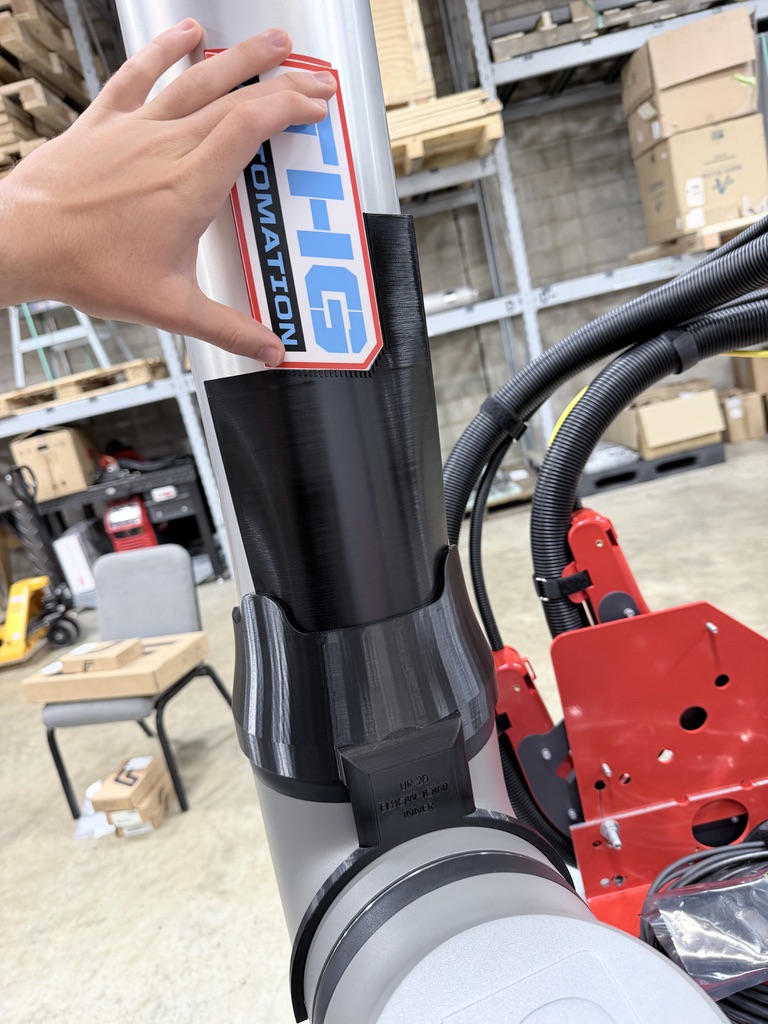
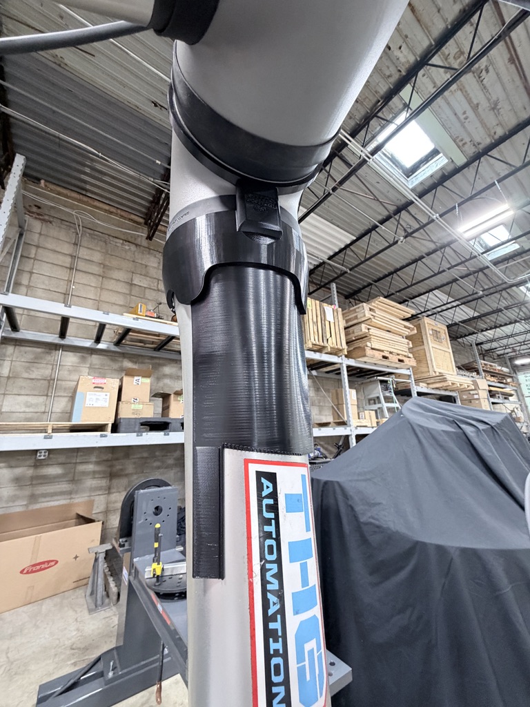
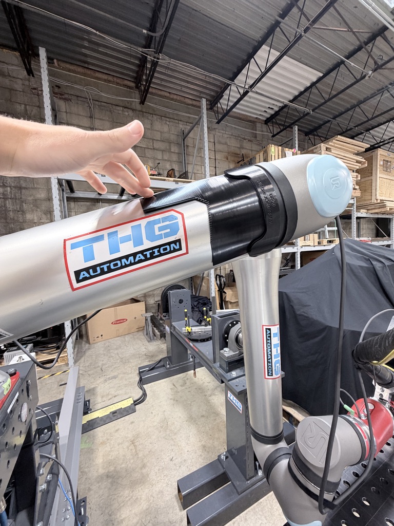
In addition to these three main projects, I did several smaller side projects to keep myself occupied. One of these was creating a system to help with applying stickers to the UR robots. At the company, they typically placed 4 logo stickers on different linkages of the robots. In a perfect world, they would be placed dead center. In practice, and when done by hand (i.e. eyeballing it), the stickers’ positions could vary greatly. So to solve this, I set out to make a 3D-printed “template”.
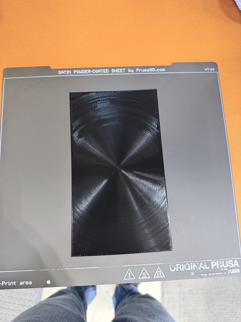
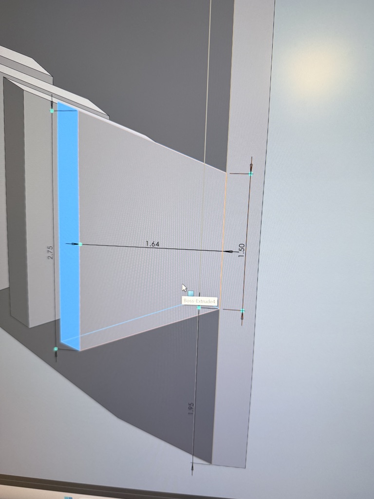
I will spare some detail in this section because the development of this part took far longer than I would’ve hoped for something so simple. Essentially, using a 3D model of a UR20 cobot, I created a shell of each robot arm linkage using surface tools in SolidWorks. Although it would’ve been easier to just cut a hole into this shell for where the sticker goes, the length of the linkages posed a challenge. They were far too big for the print bed size of our 3D-printer (>250mm). This inspired me to innovate and invent a different way. Through a lot of trial-and-error, I developed a way to 3D-print thin sheets of PETG filament that could bend and hold their shape. This was necessary so the parts could lay flat on the robot arm. I tried a couple of different infill patterns (Archimedean chords, Hilbert curve, etc.), but what worked the best was rectilinear lines parallel to the bending axis so that as the part cooled, the extruded lines would naturally warp into a half cylindrical shape.
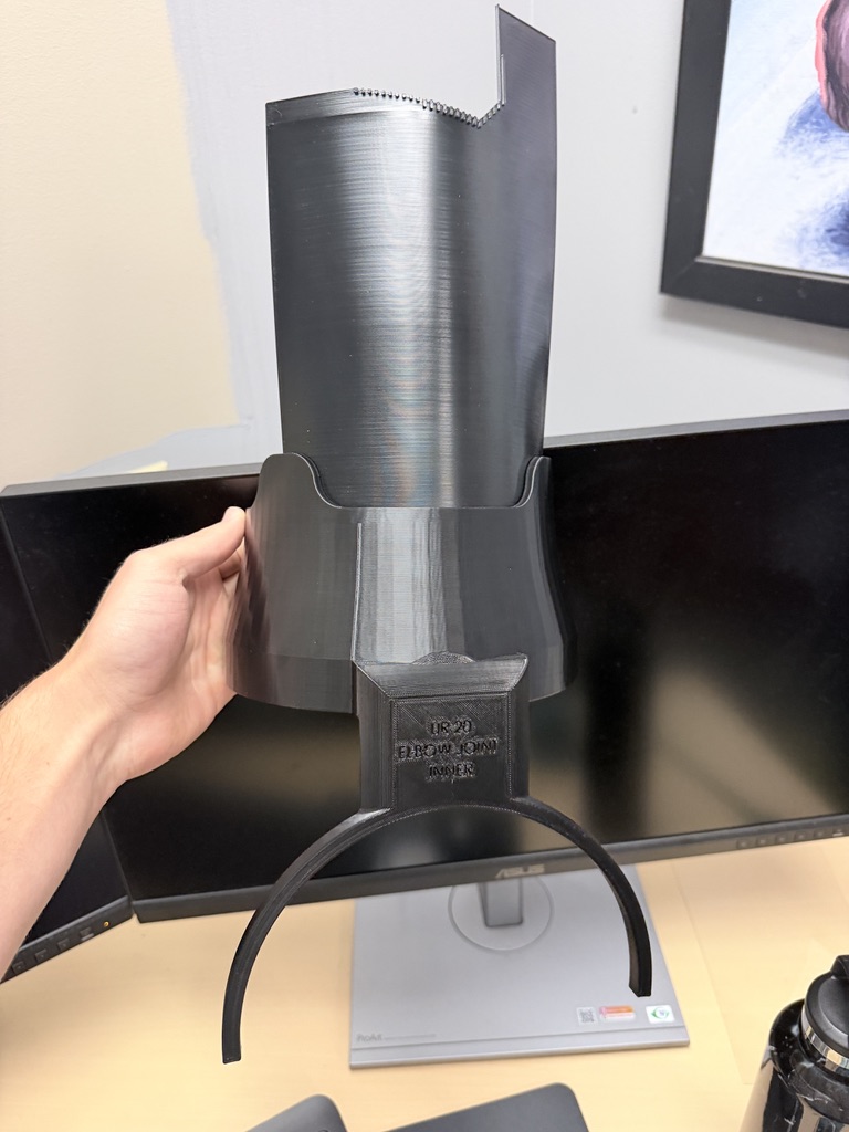
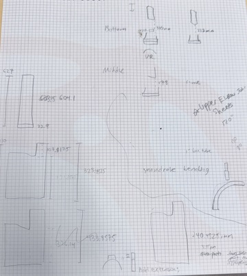
By combining these flat sheets with a custom holder part at the bottom, I created dedicated templates for each cobot joint that exactly placed the sticker in its desired spot. I used a dxf file of the sticker and projected it onto the flat sheets in SolidWorks to create exact cutouts. The math for this was a little confusing given all the different curves and bends on the robot but I was able to get it after a few tries.
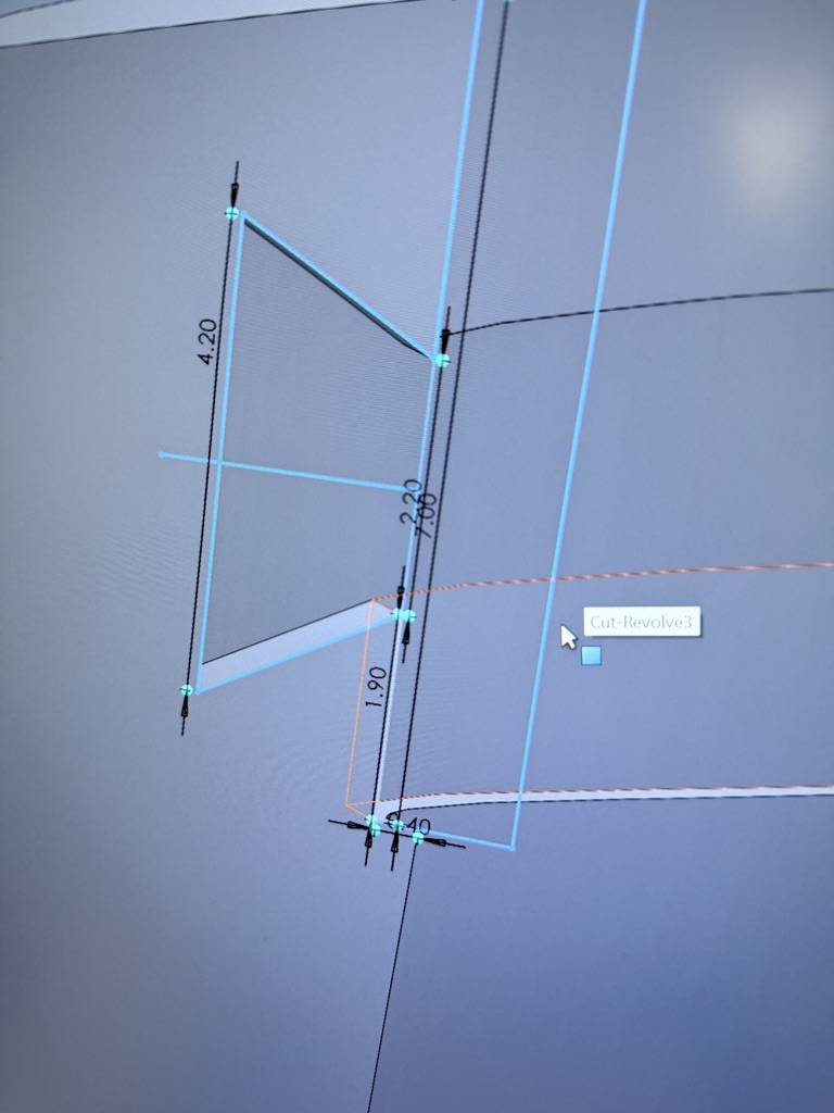
To hold these flat template sheets in place I designed this interlocking mechanism (essentially a zipper, if you can’t tell this project was heavily over-engineered for what its purpose is). The mechanism is cool as it locks the sheets precisely in place but they can be easily removed and replaced with a new one in case they are damaged or the sticker design changes later. The tolerance is a little tight, as you can see in the video below; you have to line up the little teeth carefully with the hole in the base holders.
The final result looks pretty good and I think works very well. That being said, designing these parts and modeling them in SolidWorks is incredibly tedious and overall just a pain. At the end of the day, the biggest benefit of making it all was that it taught me a ton of techniques and tricks for 3D design and forced a lot of critical thinking.
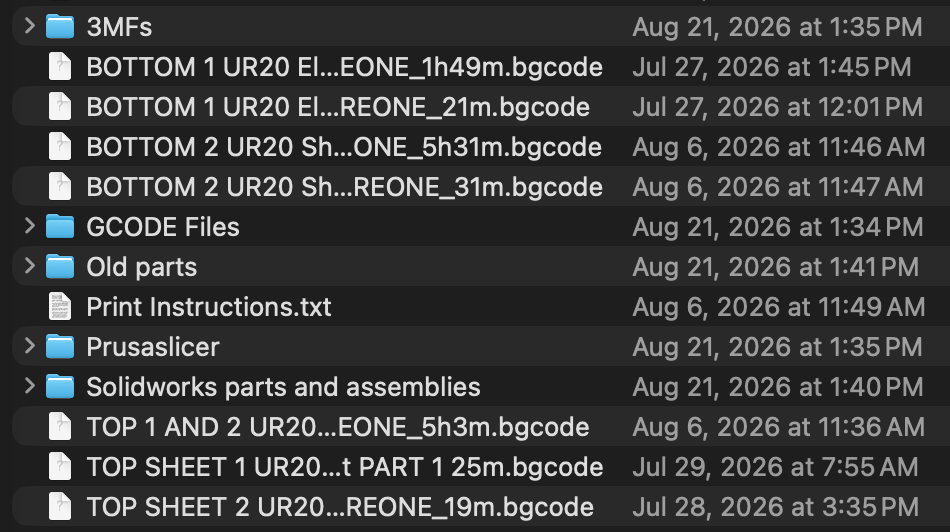
The naming conventions I used also weren’t the best, so I left detailed print instructions for all of the parts as a .txt file in the project folder (I also did this for my other 3D-printed side projects).
Side Project: UR20 Air Tube Holder
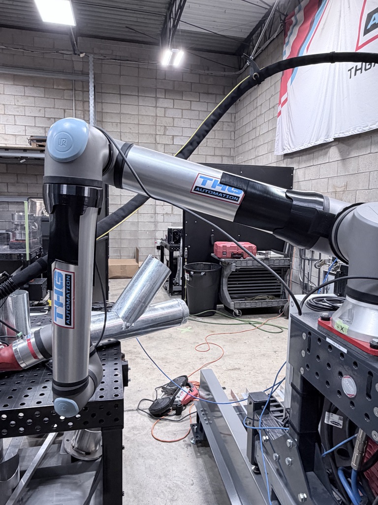
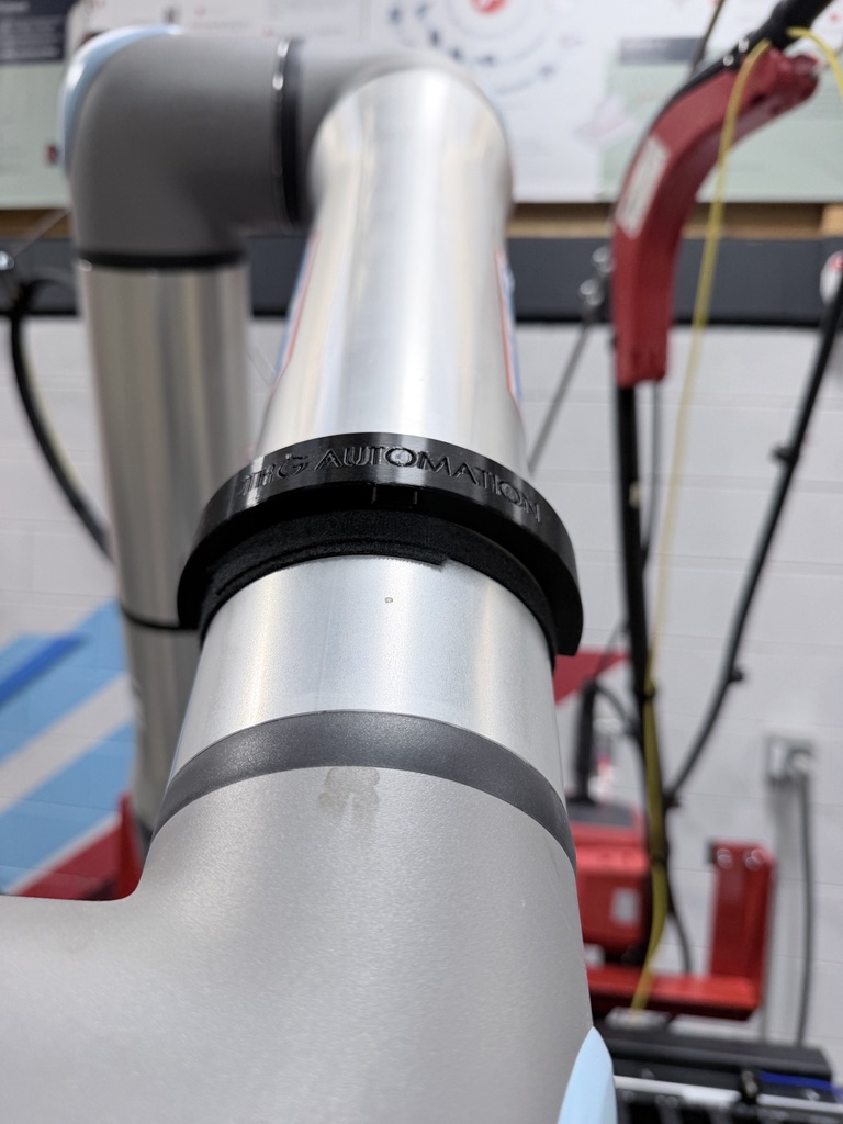
Another small project I worked on was finding a way to better hold pneumatic tubing attached to the toolhead of the robots. For the system sold with torch changing (MIG/TIG), a pneumatic tool changer allowed the robot to disconnect the torch and switch to a new one. This was all well and good but the air tubes to do this were left either flopping around or haphazardly velcroed to the robot linkages. To fix this and to make the whole setup look more professional, I set out on making little clasps to hold the tubes instead. My first idea was these large C-shaped pieces that were double-sided taped to the cobot. While this did work, they took a long time to print, there had to be different sizes for each linkage, and the tape made them semi-permanent.
After some discussion with our welding engineers, I made some major changes and improvements. By making these holders much smaller, they became “universal” and could be used anywhere on the robot. I also designed a little slot that allows a piece of velcro to be threaded through a small cavity and ridges on the bottom to hold pieces of rubber friction tape. I also adjusted the slot size for the pneumatic tubing so they would “snap” in and hold in place.
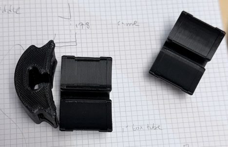
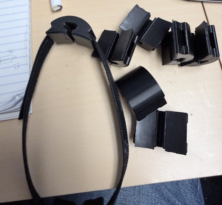
This new design worked fantastically and assembling them was kind of fun (see video below). With this velcro design, they can be tightened snugly against the robot arm and the rubber tape keeps them from moving.
They also are no longer permanent, and with enough force, will give way and move instead of potentially damaging the cobot or the tubing. Several can be printed at one time (around ~35 in only a few hours). I also left instructions for printing more and what McMaster parts to order for the velcro and rubber tape.
Side Project: Miniature 3D Models
Throughout the summer, I also created several miniature models (1/10th scale) of parts the company sells. This started as a request from one of our salesmen as a tool for trade shows or virtual calls to more easily demonstrate the system capabilities and reach. It ended up being pretty fun to make them though so I designed several. In my opinion, and that of most people who saw them, they were really cool. Unfortunately, it was perhaps not seen as a good use of resources by everyone so I didn’t get to print as many as I planned.
Initially, this all began with printing some customer part models to help with fixture design ideation. Then I wanted to see how my tab-and-slot plates fit together.
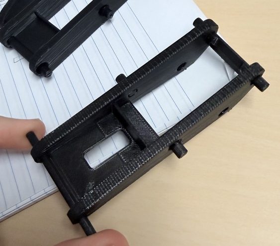
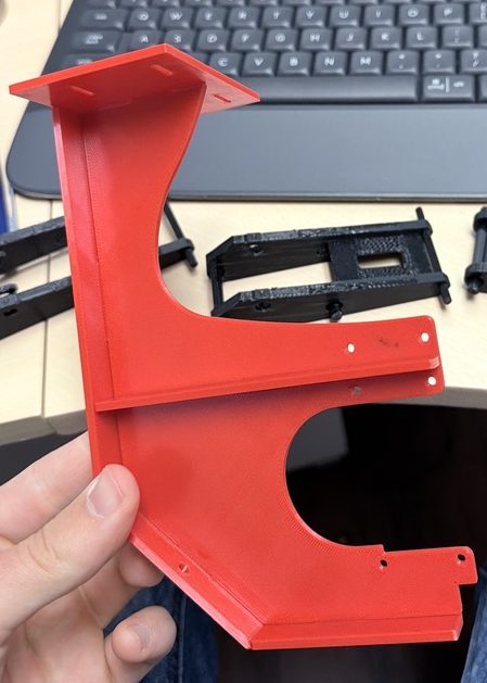
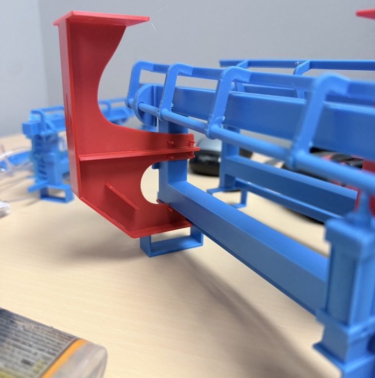
With the success of those two ventures, I moved on to printing more complicated assemblies like the blue fixtures from the first product and the side-mounting weldments with scale hardware. Note the miniature pneumatic cylinder and the rotating clamps that actually functioned (print-in-place hinge).
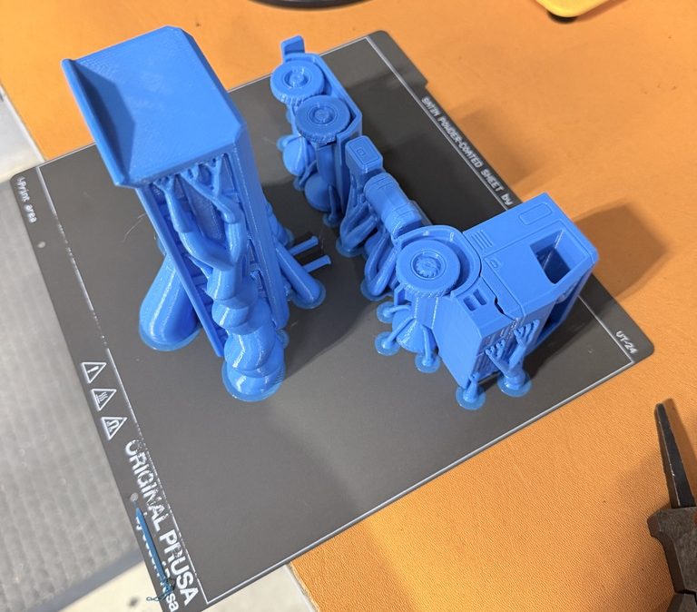
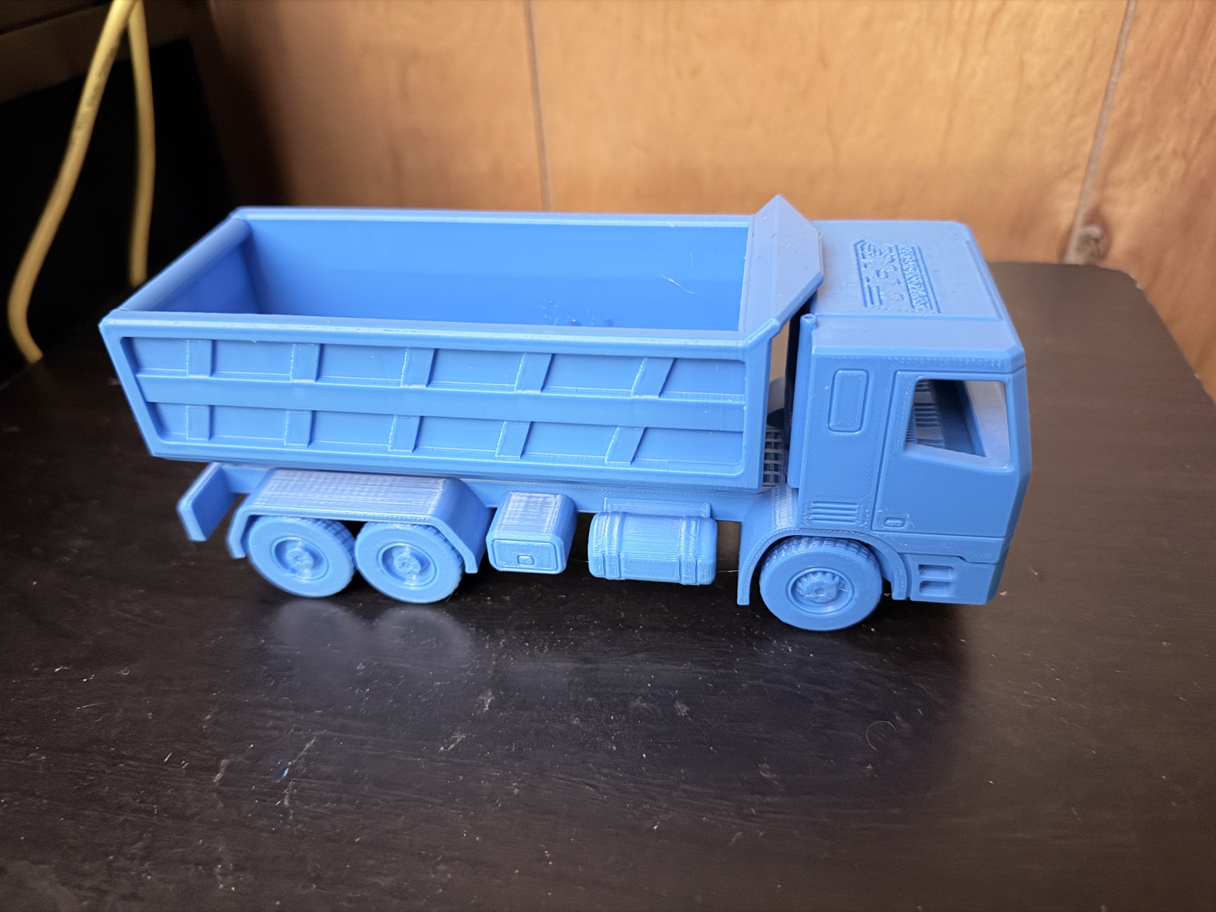
After the success of those prints and realizing the accuracy of this 3D-printer (it was a nice one), I began to explore even more. I tested lots of different support settings (organic, xy spacing) to find what worked the best to create complex geometries (in many ways an excuse to print this truck I found online, it was a fully functional dump truck with wheels and a hinging bed).
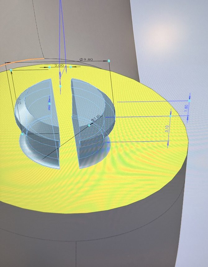
Next, I decided to make a functioning UR robot that would be entirely 3D-printed. I found a couple designs online, but they all required gluing or special hinges that were not 3D-printed or needed to use a different filament like TPU. To accomplish this, I drew and then modeled my own custom male and female snap-fit connectors.
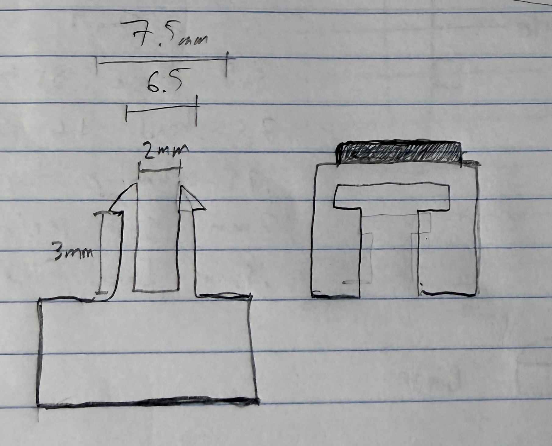
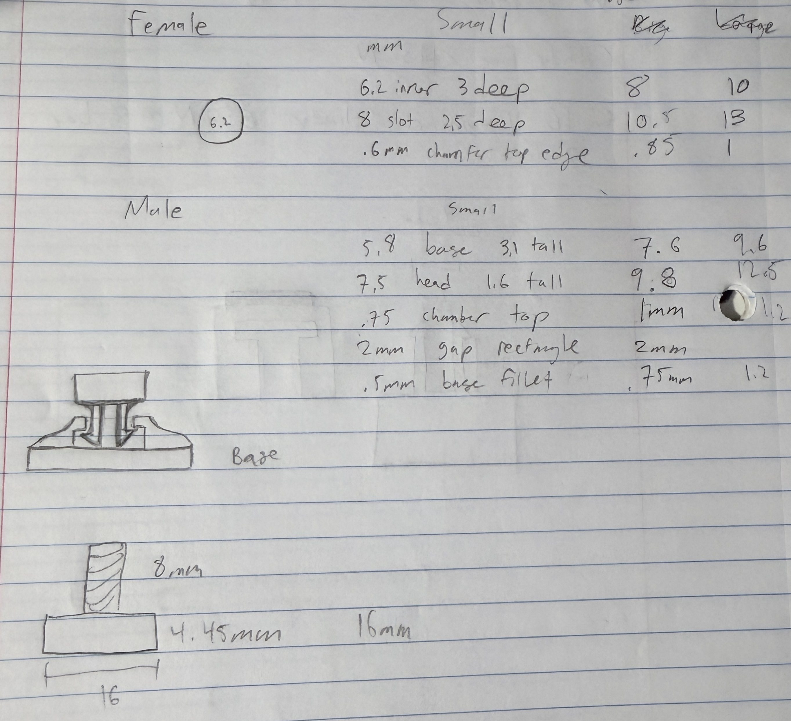
Then I split up a 3D model of the UR8 cobot in SolidWorks and added these connectors to each joint interface of the robot. The result was a really cool fully functional 1/10th scale UR8 cobot made entirely out of PETG. It prints in a little kit of 6 pieces (one for each joint and the torch toolhead). From there you just need to tap the base joint so a small magnet can be threaded in and snap all the pieces together. The pieces could be a little difficult to connect sometimes but a small pair of pliers helped this.
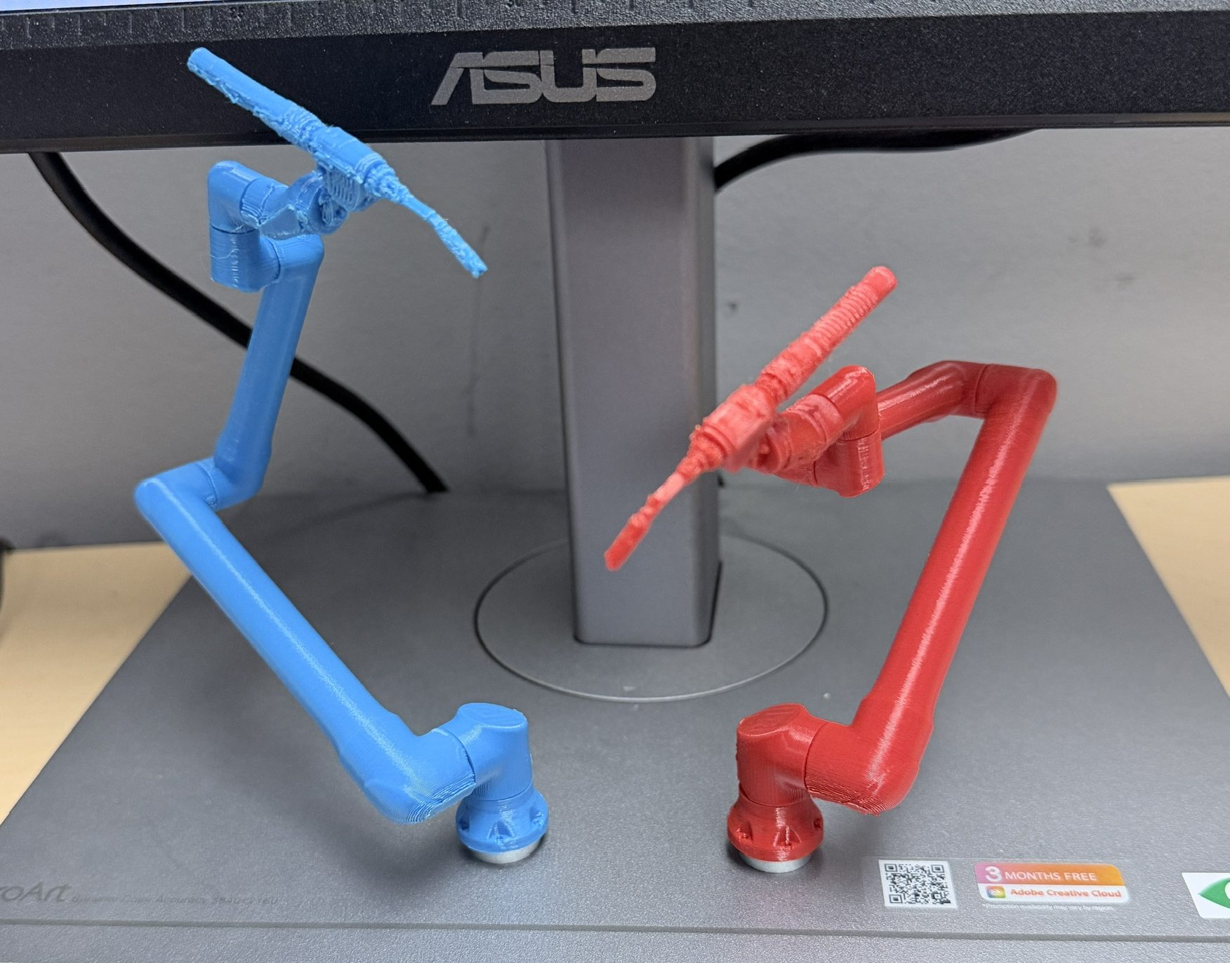
Designing these took a fair amount of work but I was able to do it in only about a day or so. I had to adjust the tolerances several times to help the joints move more easily and the magnet at the base helped lower the center of mass. It also allowed for easy attachment to any metal base and other 3D-printed parts with magnets (foreshadowing).
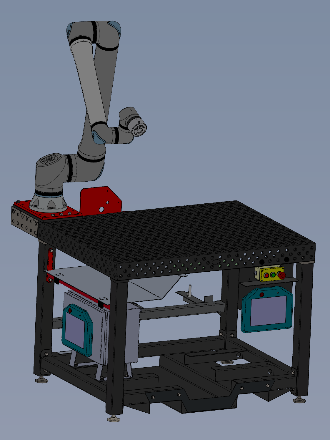
After creating the robot, I decided to print a miniature table setup. This turned out really cool but it took a fair amount of problem solving to make it actually printable. The hole pattern for the top of the table required it to be printed separate from the base and I then printed the base sideways to reduce the amount of supports. I also printed the cobot outrigger top plate separately so I could embed a small magnet inside. By carefully choosing the orientation of the magnet, I set it up so that the mini UR robots would snap into place to mirror the real-life design.
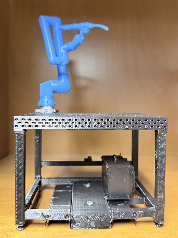
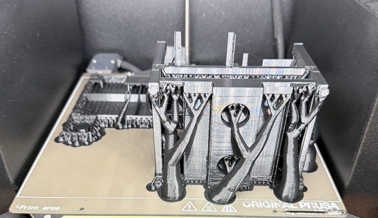
Although pretty cool on its own, it was more of a paperweight than something actually useful. To fix this, on my last day of work I printed a little multicolor “scale-block”. This block was a 1/10th scale 1 x 0.5 x 0.4m part (100 x 50 x 40mm) with a color change 20mm up to split it even further virtually. By combining this part with the mini table, one can accurately see if a customer part could feasibly be reached and welded by our setup.
As I mentioned earlier, for project 2 I also 3D-printed the dual-axis positioner and fixtures to see how they might end up looking in real life. By printing them at 1/10th scale, I could also see how the cobot would line up with the parts. See the following photo and video for a demonstration.
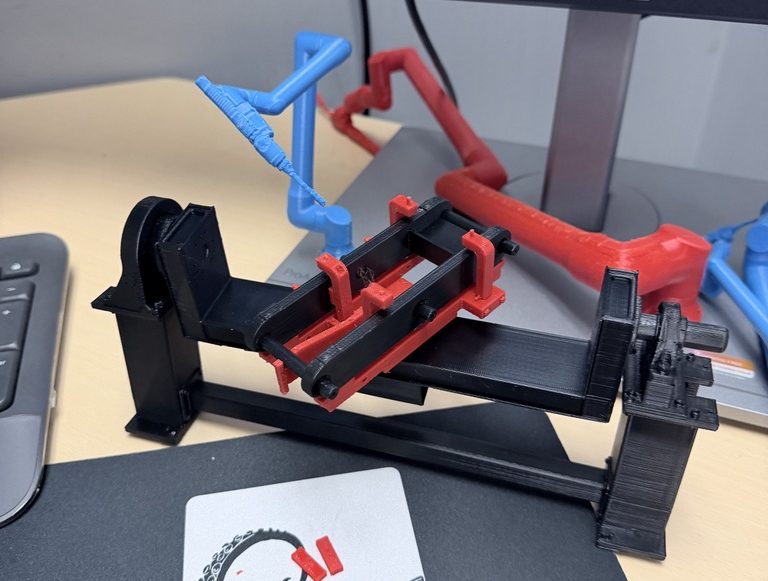
Printing this positioner was also a bit of a challenge; I had to split it into two parts and embed magnets to make it functional. I also used one of the custom snap-fit connectors I designed for the UR cobot prints so the upper piece could rotate.
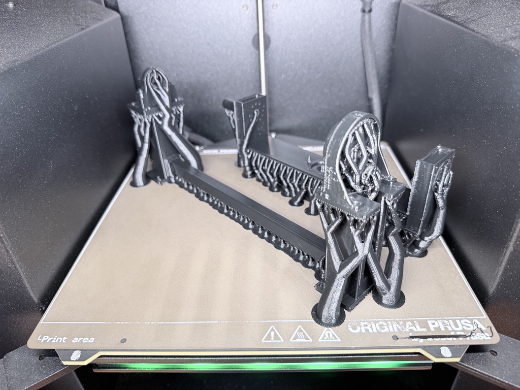
Honorable Mention: Argon Gas Can PSI Magnets
Another cool little project I worked on was these small PSI label magnets for the argon gas cans. Argon gas is used in welding as an inert shielding gas to protect the molten weld pool from oxygen, nitrogen, and moisture in the air. It ensures a stable arc, helps to prevent oxidation, and produces cleaner/stronger metal joints. This is all well and good, but if you run out of gas it won’t have any of these benefits! To help know when to order more gas, these little magnets can easily be slapped onto the large metal cans to visually and brightly label how much gas is left. There is a little pressure dial showing the exact amount on the top of the can but it is easy to ignore and forget about.
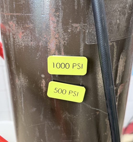
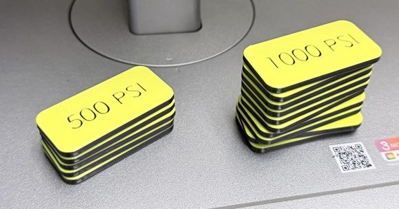
Making these was cool because it required two print pauses, one to embed a magnet and one to change the filament color. I designed and printed these over the course of about 3 hours.
Honorable Mention: Cupholder and Hex Bit Organizer
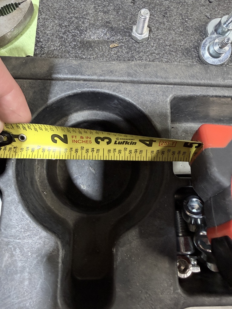
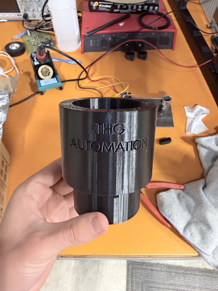
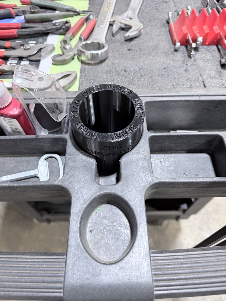
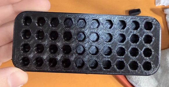
I 3D-printed several things to help make our production team’s job easier. For example, they wanted a small cupholder to hold their pencils and pens better on the tool carts. I also printed some hex bit organizer trays to hold loose bits.
Honorable Mention: Tripod Quick-Release Part
One other cool reverse-engineering project I did was this tripod part for our marketing team. They had lost the little piece that allows a camera to easily connect to a tripod and needed a new one.
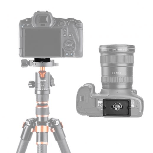
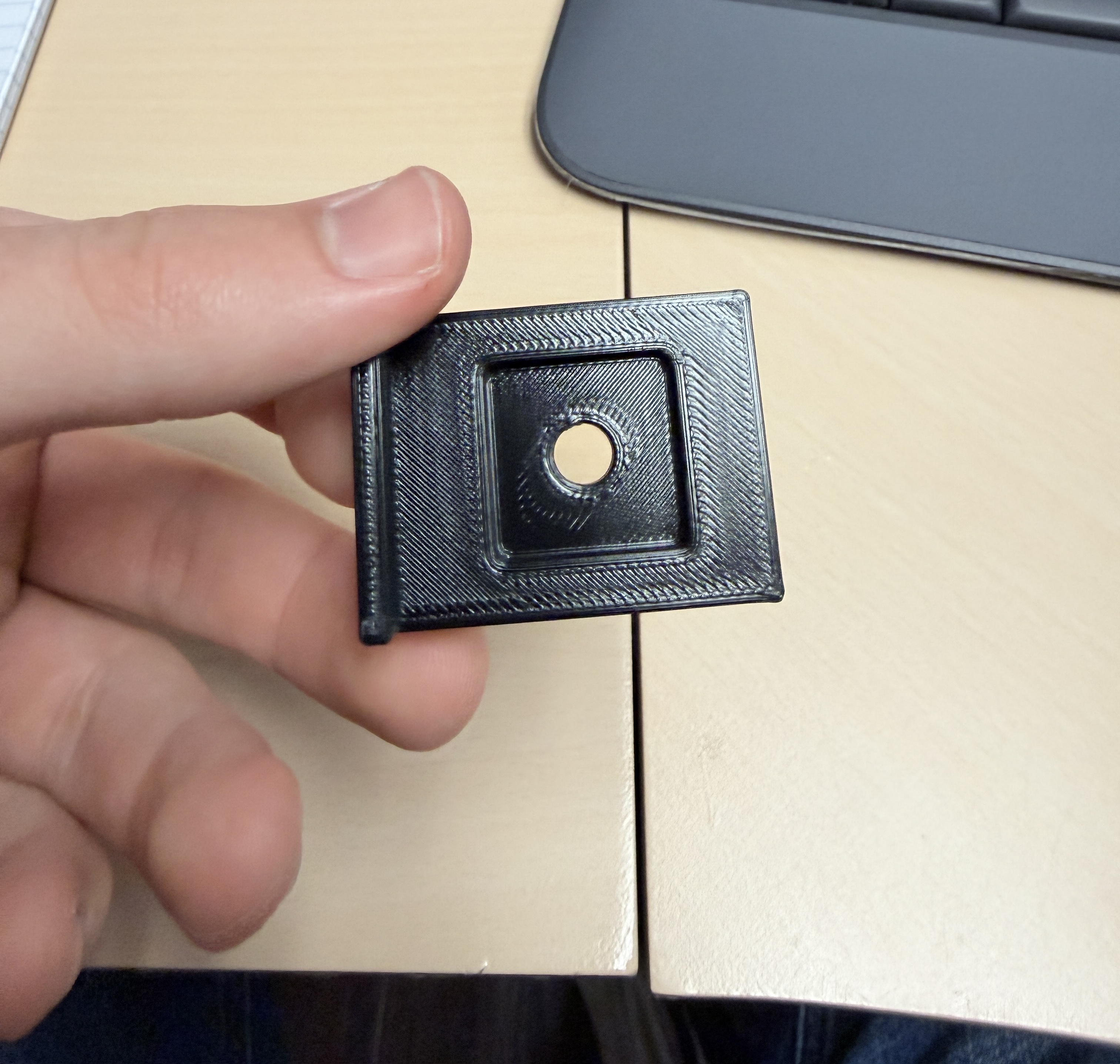
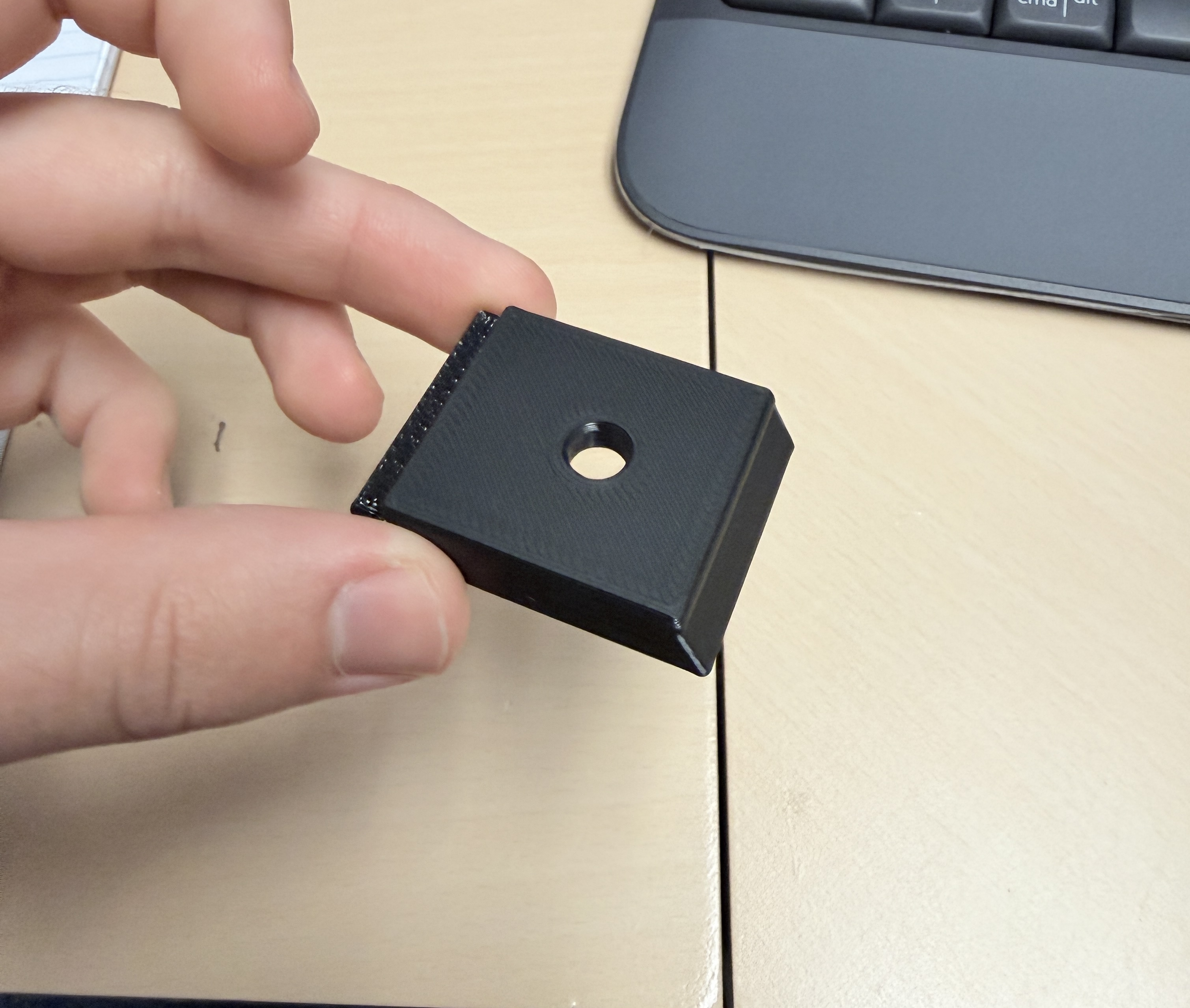
This seemed like an easy enough project and a perfect thing to 3D-print. By looking at some existing parts online and measuring the tripod base with a dial caliper, I successfully modeled and printed a replacement part in only about 2 hours.
Final Thoughts/Recap
Overall, this was definitely my favorite internship I’ve had. It reinforced my passion for mechanical design, creative problem solving, additive manufacturing, and that I chose the right degree for undergrad (mechanical engineering). Despite only having 11 weeks between graduating and returning to Purdue for my master’s program, I feel like I really took advantage of the opportunity to create some awesome things and contribute as best I could. I am very grateful that they gave me a chance to work there and that I was trusted to work on all of these complicated projects.
