Undergrad Research
On a whim, I decided to join a research project for the last semester of my undergraduate degree. I’d always thought it may be interesting to do one, but never really had the chance until then. After applying to a couple, I ultimately accepted an offer to work on an open-ended robotics idea with the Purdue Manufacturing and Materials Research Lab (MMRL).
Project Definition
The main goal for my work was to create content for a new section of a Purdue mechanical engineering graduate class, ME59700. The topic was autonomous cell-based manufacturing using a 3D printer, Raspberry Pi, and robotic manipulator arm.
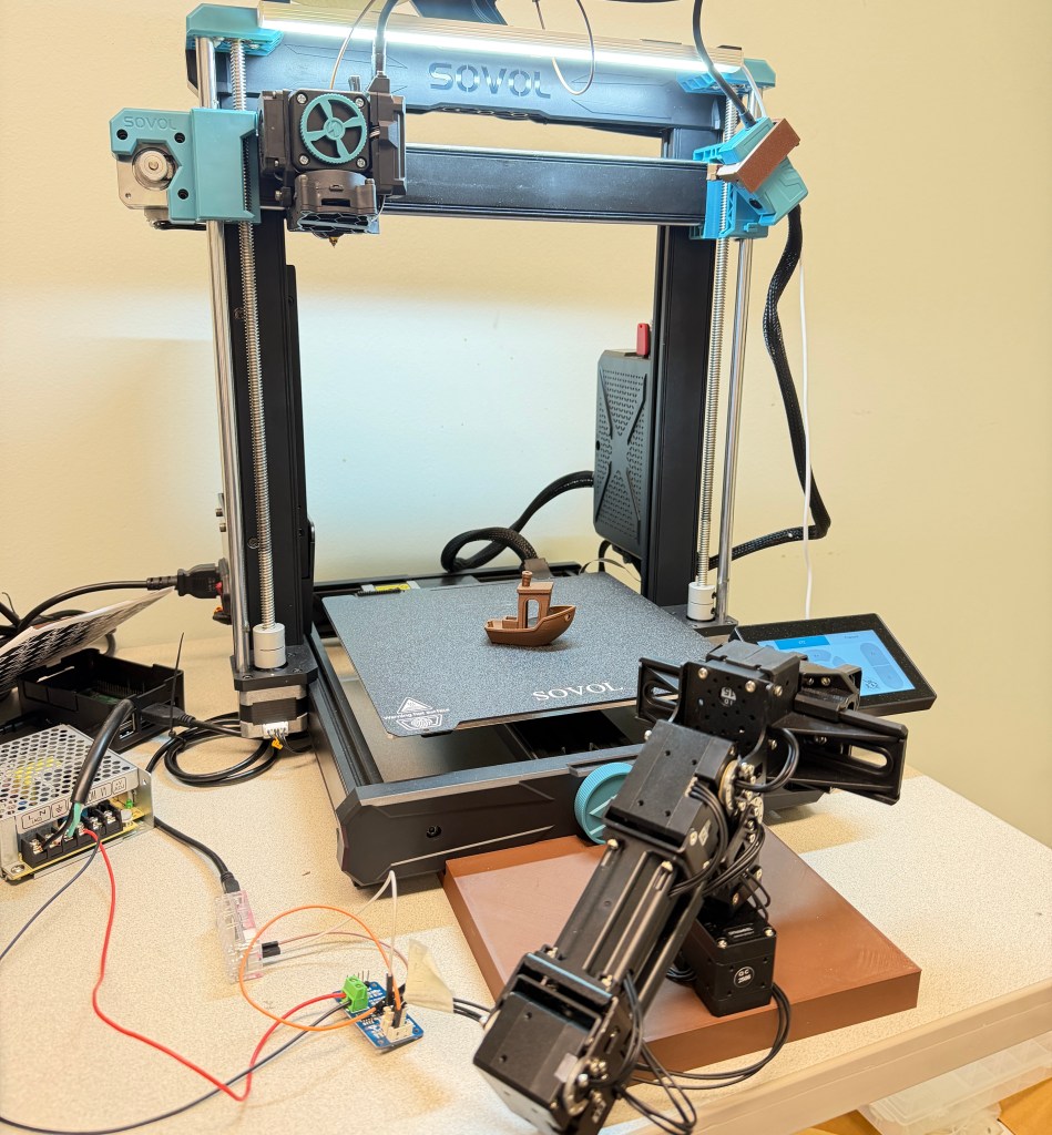
I completed many small projects throughout the semester, so they are organized by month, along with a recap and final thoughts at the end.
For more info on specific code and setup, please visit my two GitHub repositories for this project:
January – 3D Printer & Robotic Arm Research/Ordering
The main thing I did in the first month was researching what 3D printer and manipulator arm we needed to order for the class. The budget wasn’t firm, but it ideally would be less than a few thousand dollars since ultimately this class would need multiple setups for different students to learn at the same time.
Ultimately, we decided to order the Sovol SV06 ACE Printer since it had a built-in camera, reasonable price, and extensive API documentation.
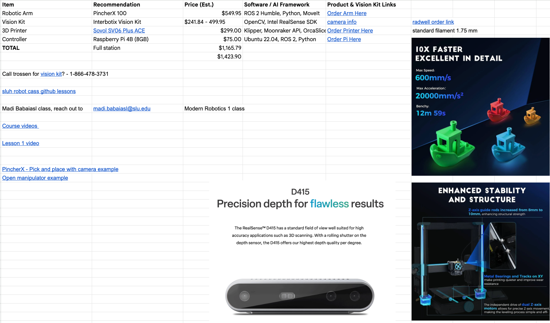
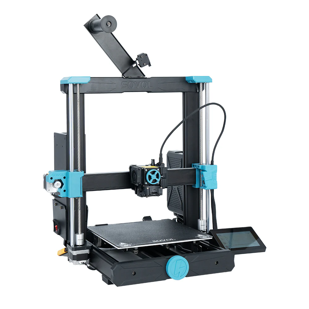
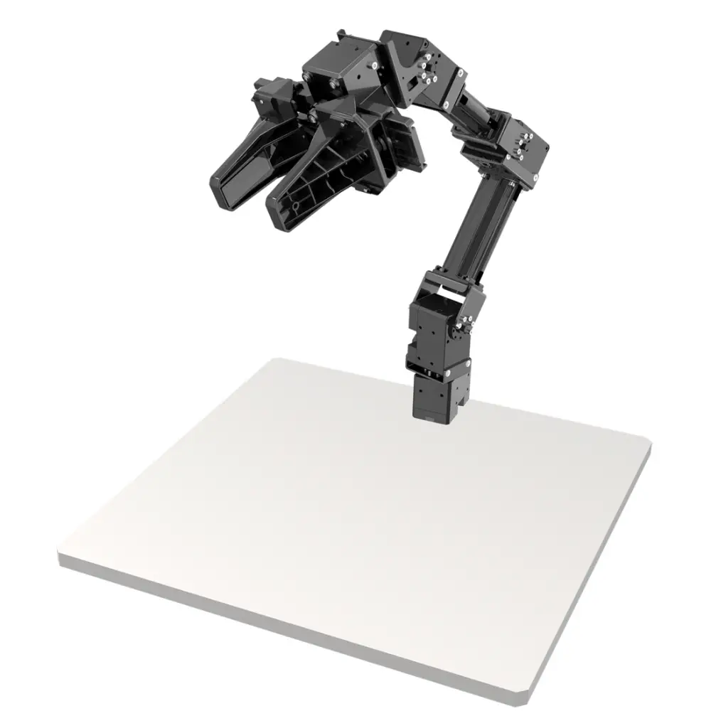
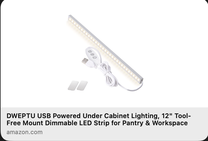
The Open Manipulator-X robot arm was chosen because of its open-source software, payload size, and existing documentation. Also, an LED light bar was later purchased ($6) to improve camera lighting.
February – Printer API, MTConnect Code, Robotic Arm Assembly
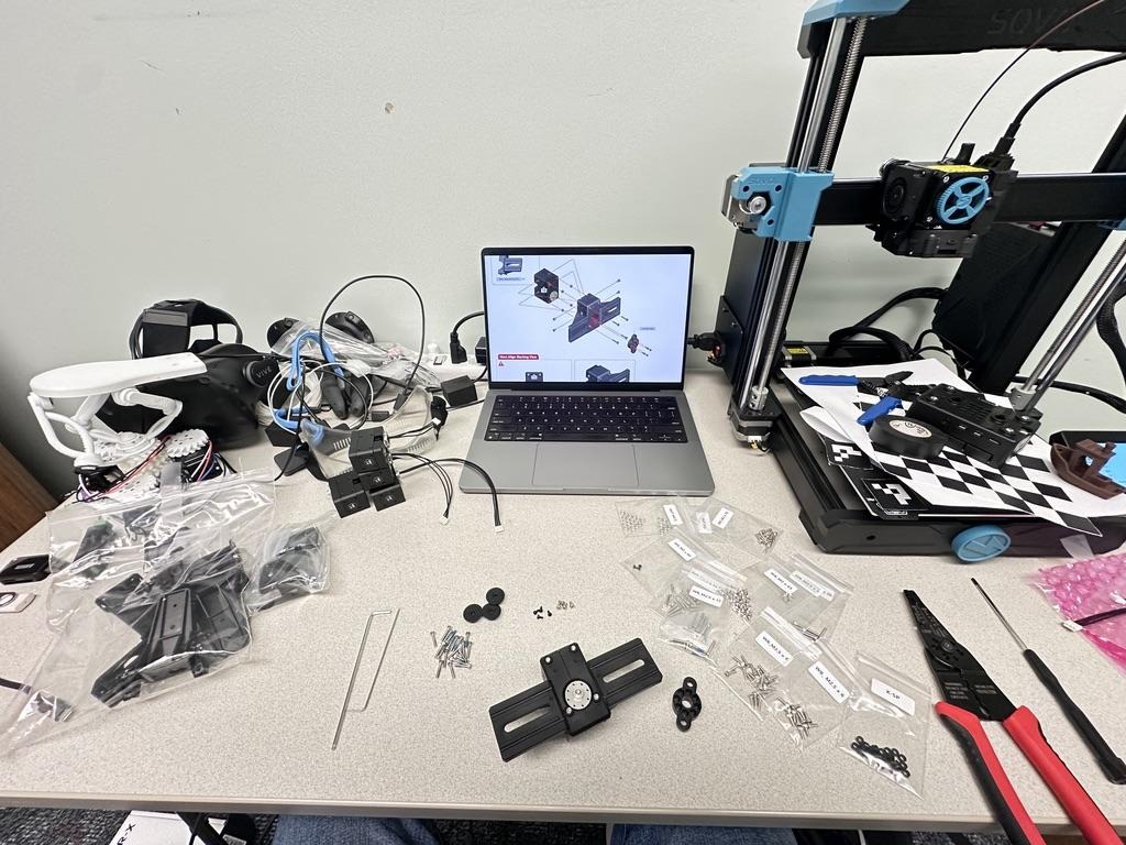
In February, I focused on the groundwork for the project. Namely, I focused on connecting to the printer over a local network connection, designing the flow of data for the system (MTConnect), and assembling the robotic arm.
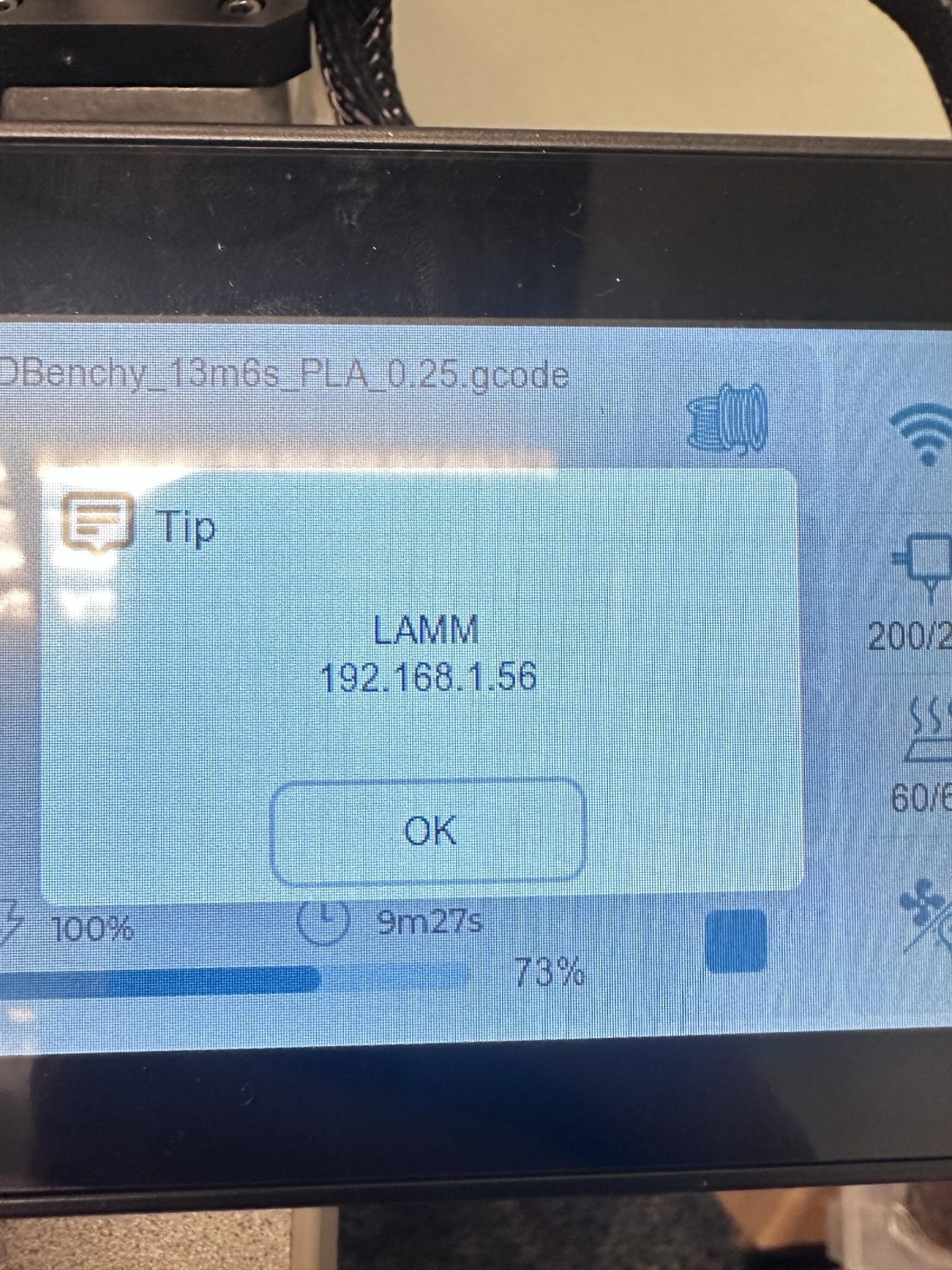
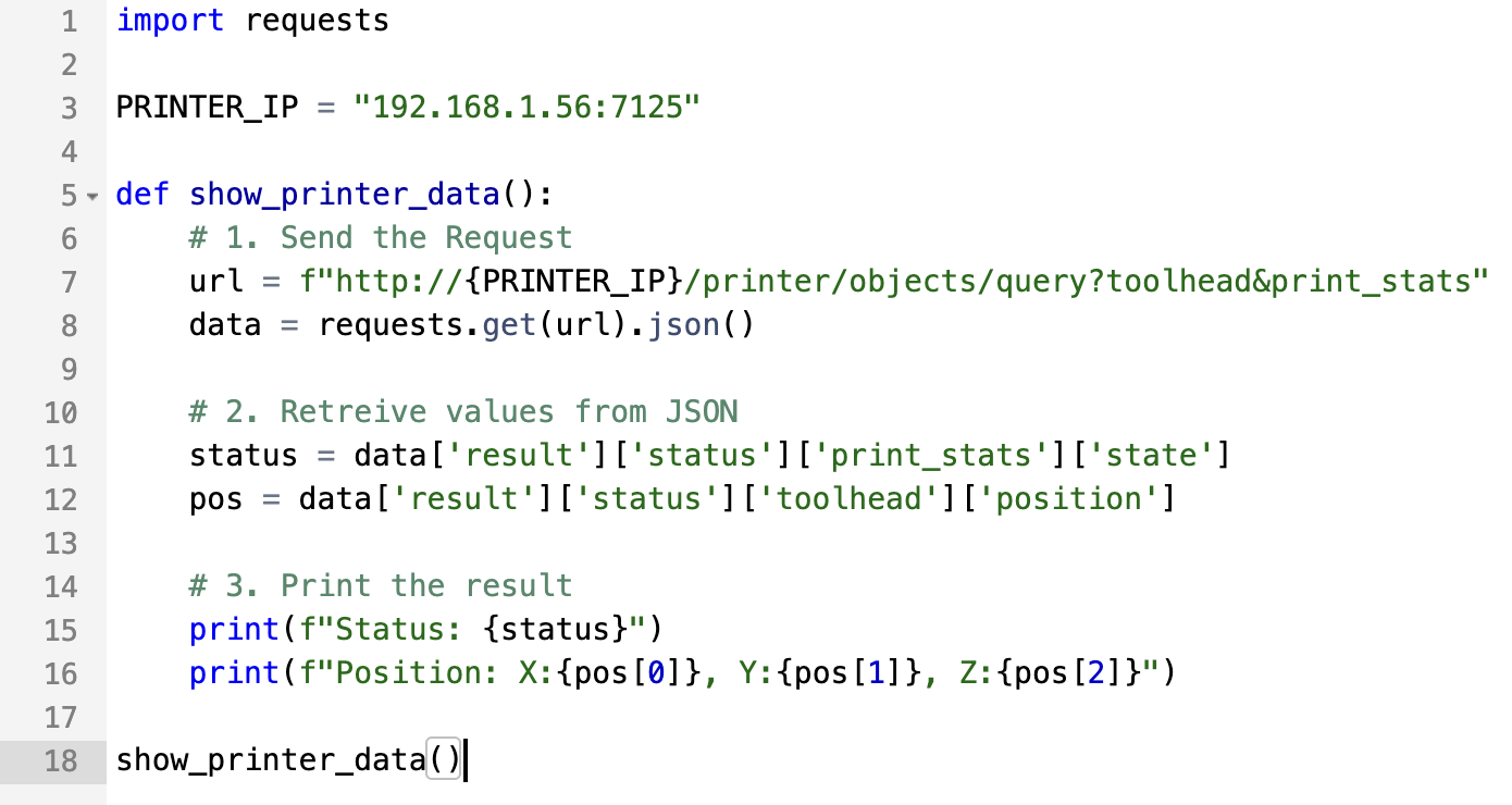
The integration architecture seen in the diagram below outlines how the middleware MTConnect streams data from the printer to any device connected to the same network. MTConnect is an open source communication standard designed to connect manufacturing equipment and software. It uses an adapter and agent program to translate machine data into an easily readable XML format for other devices.
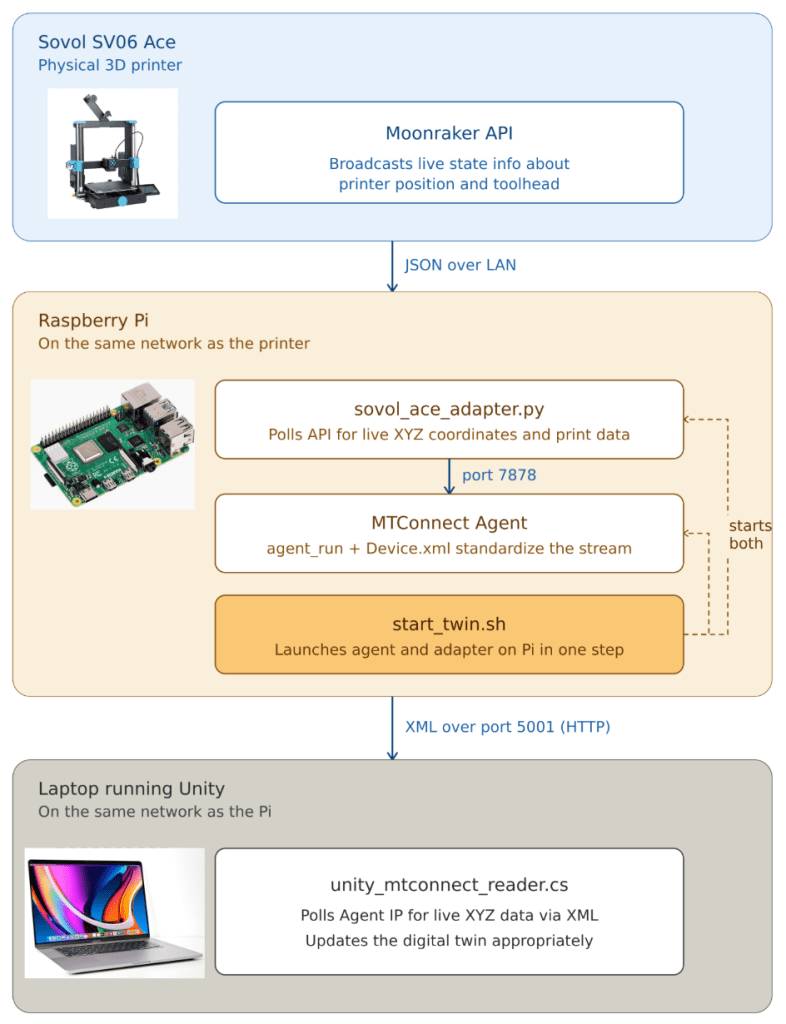
This pipeline streams live toolhead coordinates from the printer to the Unity digital twin, organized into four distinct layers to ensure low-latency communication and data integrity:
- Hardware Interface: The printer serves hardware state and toolhead coordinates as JSON objects via the Moonraker API (an open source 3D Printer API).
- Middleware (Python Adapter): The
sovol_ace_adapter.pyscript polls the API, parses the toolhead position, and transmits the data to the Agent on a separate network port. - Standardization Layer (MTConnect Agent): The
agent_runbinary processes the incoming data stream according to the definitions inDevice.xmland hosts an interface on another separate network port. - Visualization Layer (Unity): A C# implementation polls the Agent’s XML feed over a local network connection and applies smoothed transforms to the virtual model (developed later during this project).
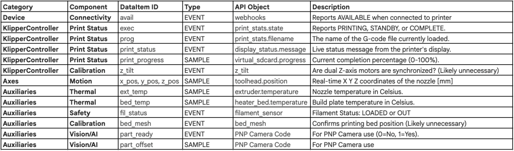
Below is the table outlining the different XML objects from Device.xml I created for this project. The MTConnect agent program sends all of this data from the printer to the local network so it can be used for other program purposes.
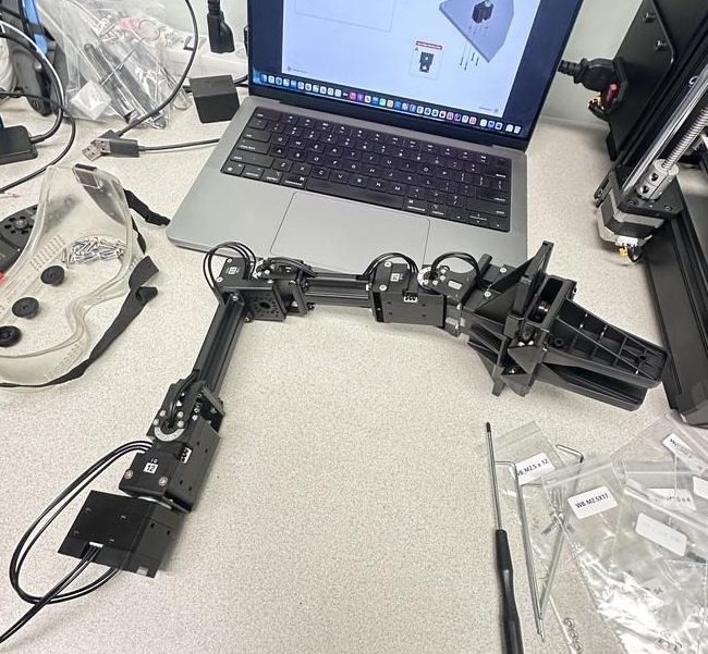
The assembly guide for the robotic arm can be found here and it took me about 3 hours to build the arm from the kit. The instructions are detailed but quite tedious and it is easy to make mistakes such as attaching the incorrect cables to certain motors.
March – PNP Camera Algorithm Attempts, Custom Angled Camera Mount, Digital Twin CAD, Unity MTConnect Integration
Despite spring break, this month was a busy time for this project and was when things started to come together. The first project was trying to use the built-in 3D printer camera to track parts on the print bed and their displacement. The original idea was to use a PnP (Perspective-and-Point) computation algorithm. Unfortunately, this proved infeasible as it was likely doomed from the start. A combination of camera quality, mounting location, and space for the manipulator arm made the code I developed both as impractical as it was inaccurate.
While this could be discouraging to some (myself included), the weeks spent on this were not a waste of time as they led to many successful ideas such as a low angle camera mount and live object projection to the digital twin (see April).
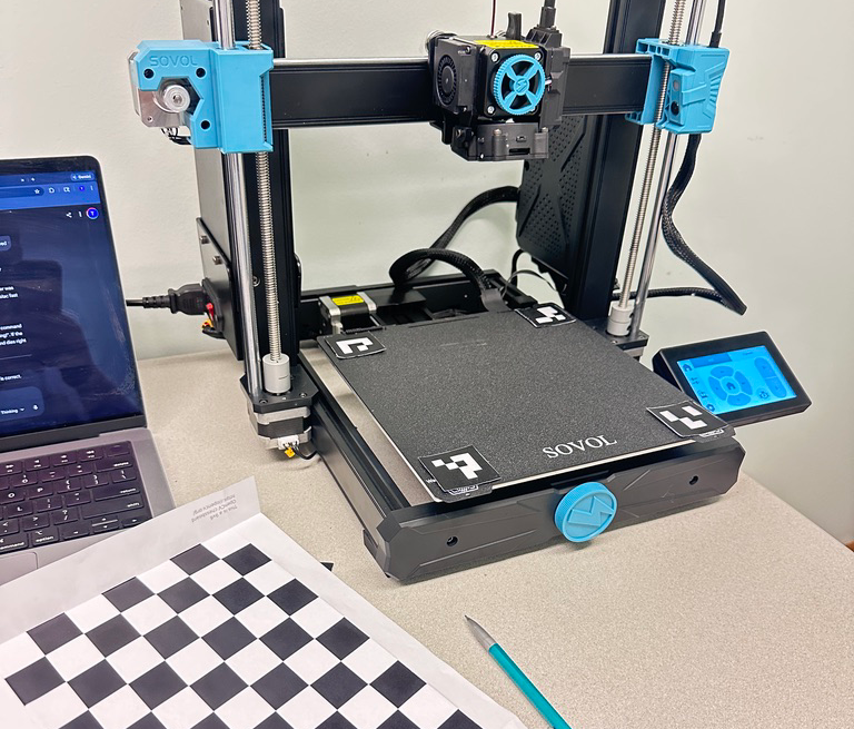
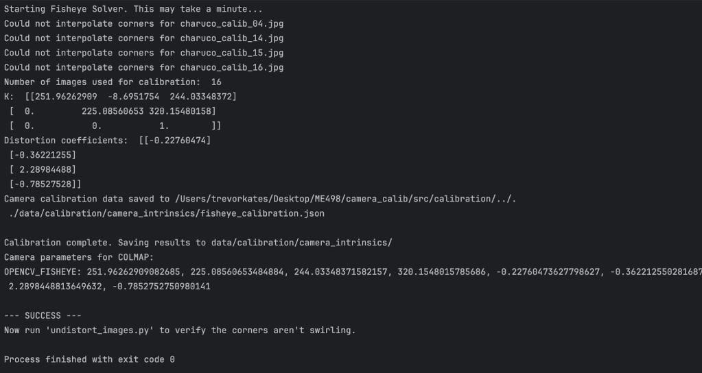
The algorithm uses a checkerboard to calibrate the camera’s fisheye lens into a flat image. From there, it uses 4 corner markers to project a grid onto the print bed. Unfortunately, the camera quality was not good enough to accurately recognize the corner markers which rendered the part tracking very inconsistent. These photos depict the file setup and calibration matrix.
The camera on the printer has a fisheye lens (wide-angle view). To calibrate this into a flat image, you need to use a checkerboard pattern to calculate how distorted the picture is. This method uses a ChArUco board (a special checkerboard that has characters in each square). See this GitHub for more info on how it works. It needs about 20 photos of the board in distinct positions with a fixed camera. Since we have a side angle of the board and not a clear overhead view, this is tougher to accomplish.
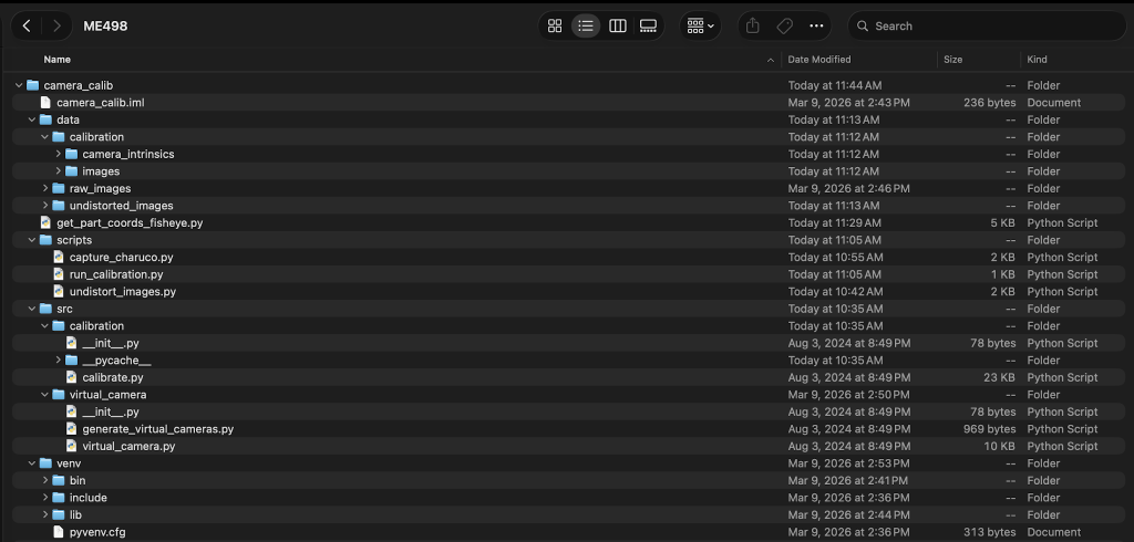
A calibration Python script then gathers parameters for the 142° fisheye lens. This script generates a K matrix that defines focal length and distortion coefficients that help straighten out the image.
Lastly, a script runs to generate a virtual grid on the print bed, detect corner markers, and project the estimated object position in reference to an origin point.
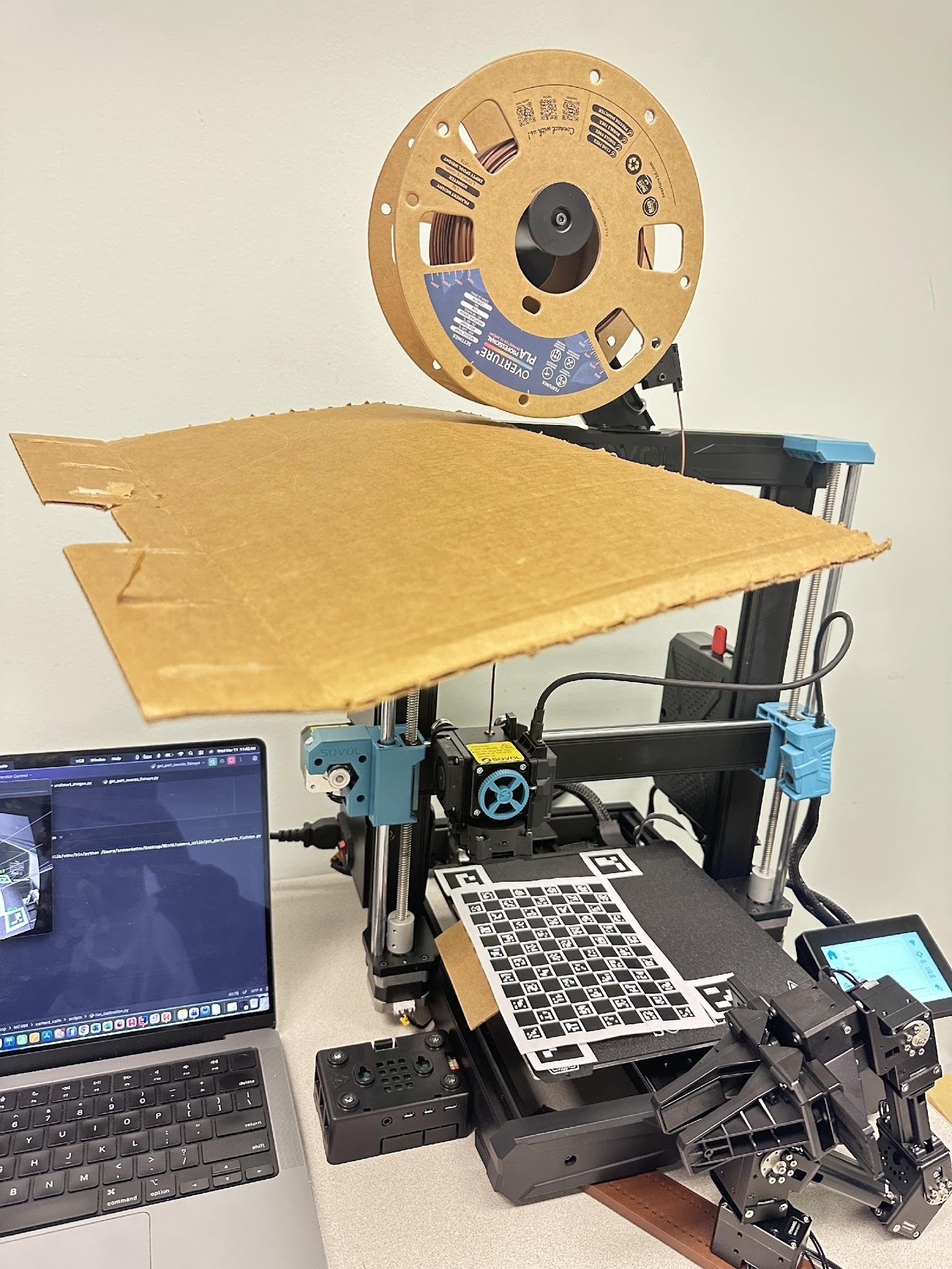
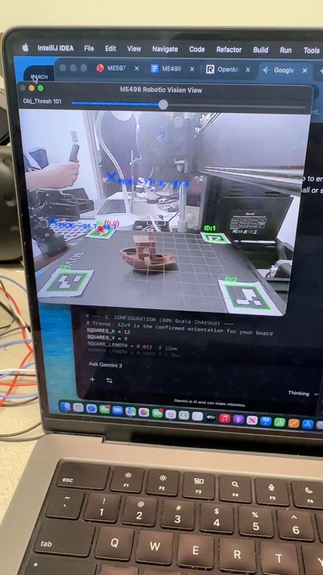
Some of the common issues this code could not overcome, as mentioned earlier, were lighting glare affecting calibration, ID markers taking up too much space, and camera position affecting print size. The cardboard in the photo above was my attempt to block out some lighting glare from the overhead fluorescent lights. The following video shows some of the code in action tracking a part on the print bed.
All of these issues sparked an idea in my head to find a way to mount the camera at a lower angle. The printer is designed to have the camera at a flat perpendicular angle to the print bed. This is great for monitoring prints but really sucks when you want to have an overhead view of the print bed.
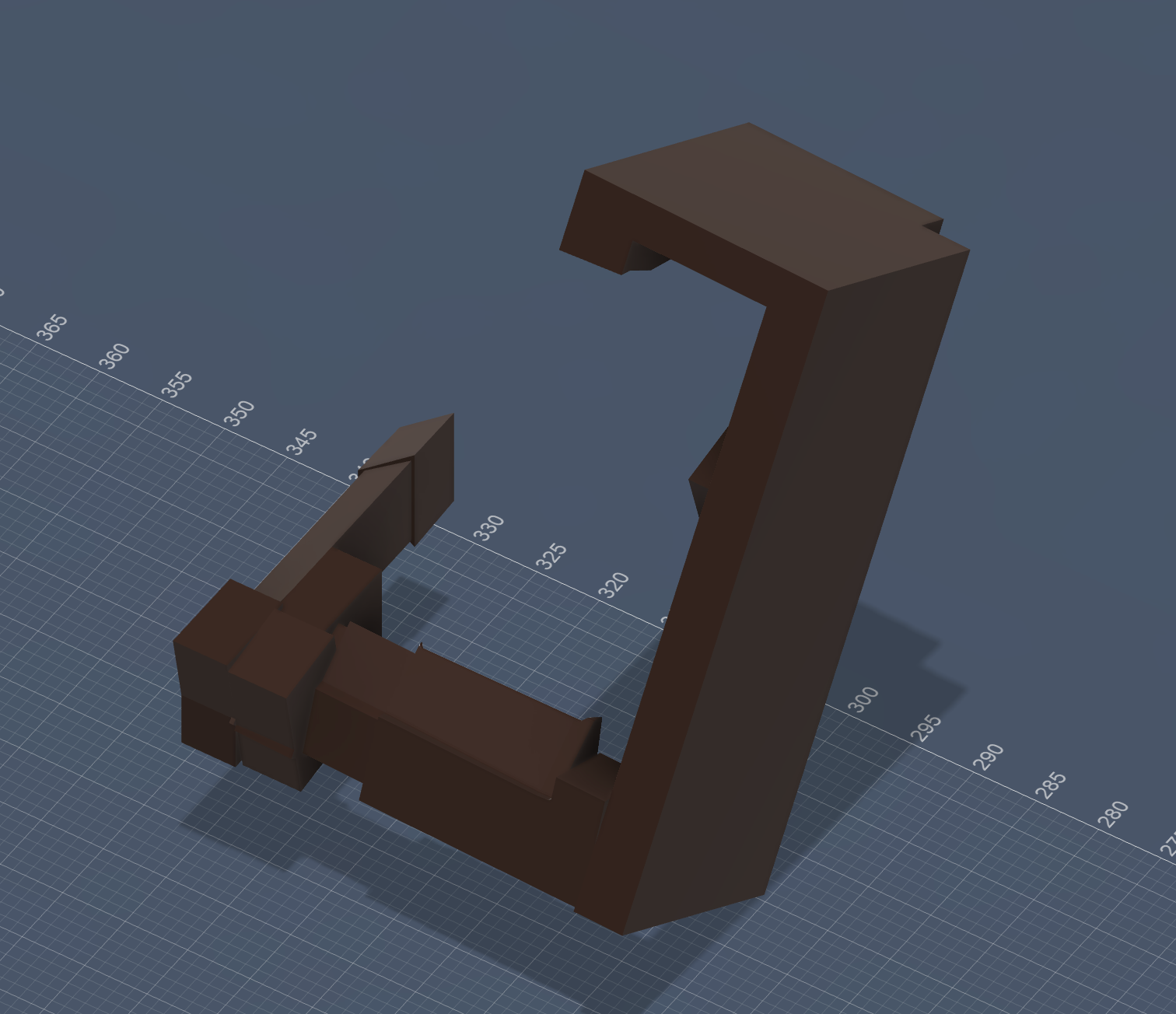
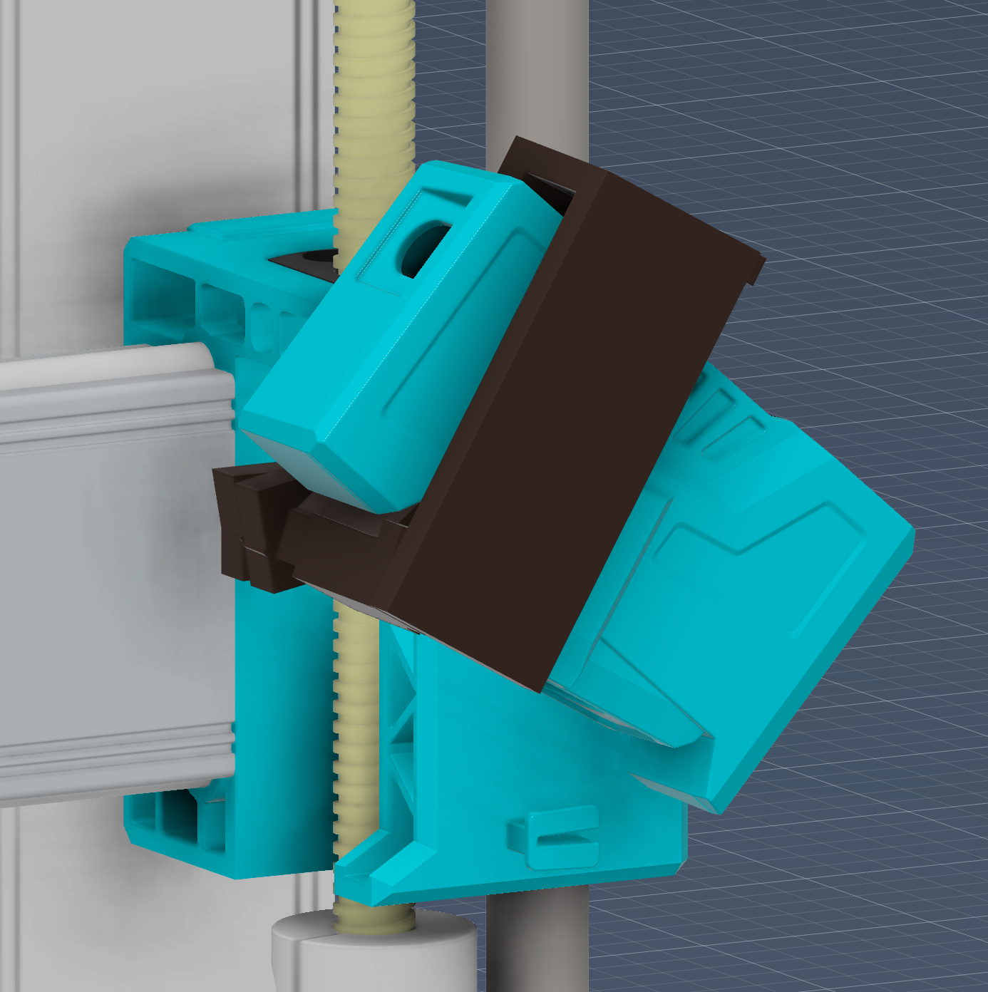
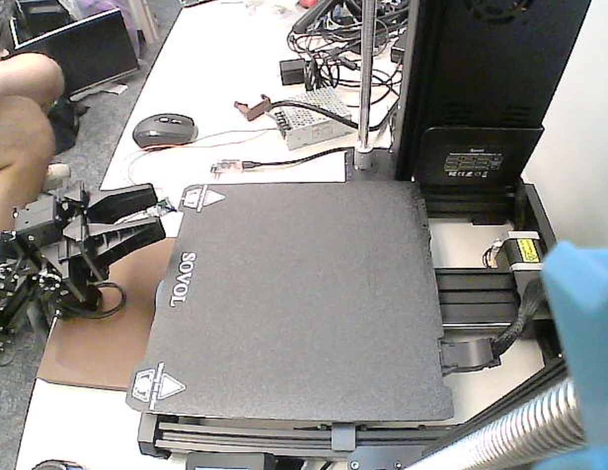
To combat this, I designed this somewhat strange and overcomplicated part that plugs into a notch in the gantry and holds the camera casing at a lower angle. It worked pretty well and gave a much better view of the print bed in the image below.
The next big step in the project was creating a digital model of the 3D printer to actually put all the API data to use. This digital model is called a “digital twin” as it is a nearly exact virtual model of the printer. One benefit of the Sovol Ace SV06 printer is its CAD file is readily available for free download. Unfortunately, this file is not organized in a way conducive to making a digital twin. Fixing this required a somewhat painstaking process of manually sorting and grouping components into parts that should move with the gantry or remain stationary. I divided it into 4 components: the gantry arm (+Z), toolhead (+X), print bed (+Y), and the remaining stationary frame. The custom low angle camera mount was attached to the gantry arm to ensure it moves correctly. The Fusion 360 CAD file was then exported into Unity as a .fbx file to maintain this file structure.
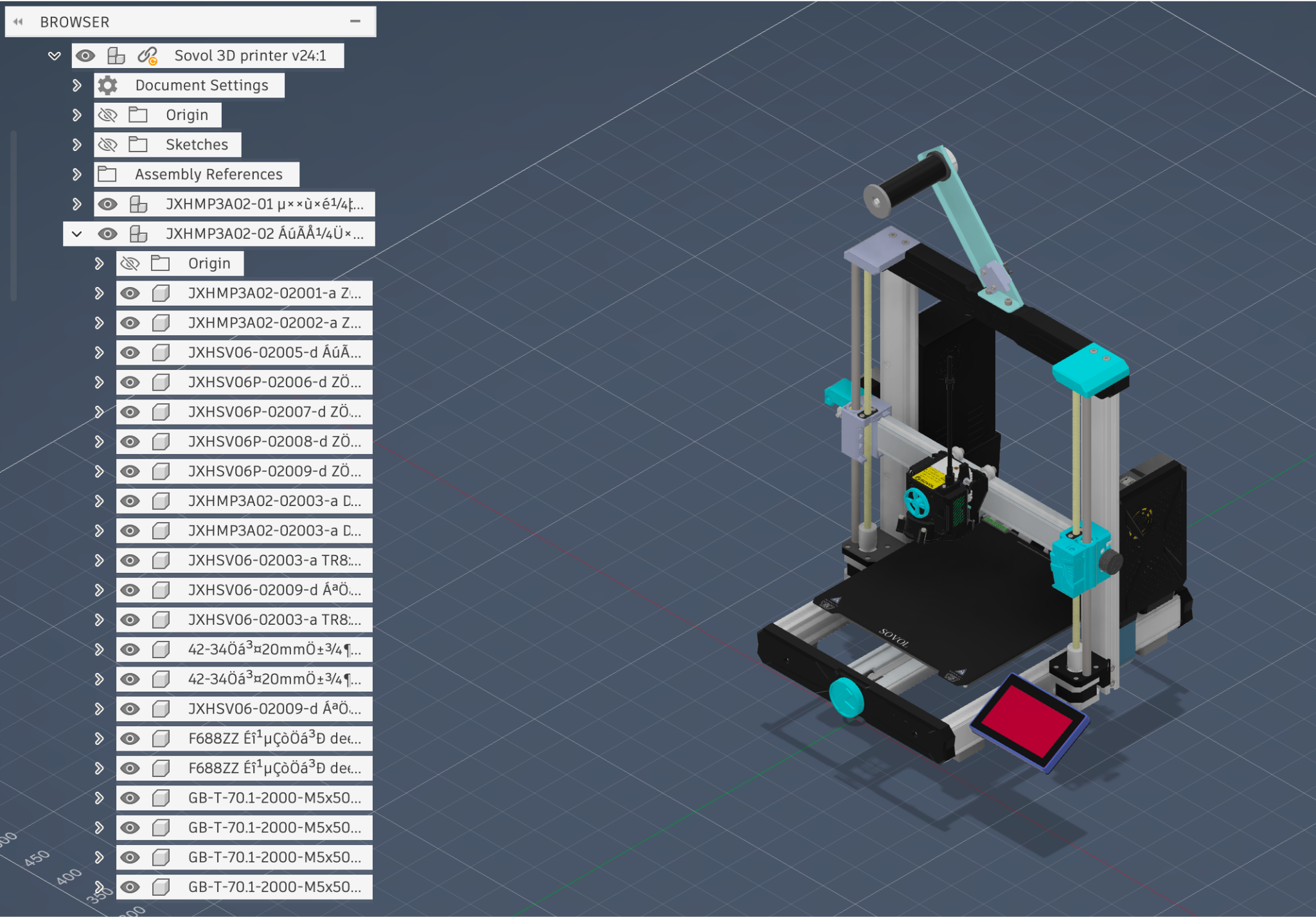
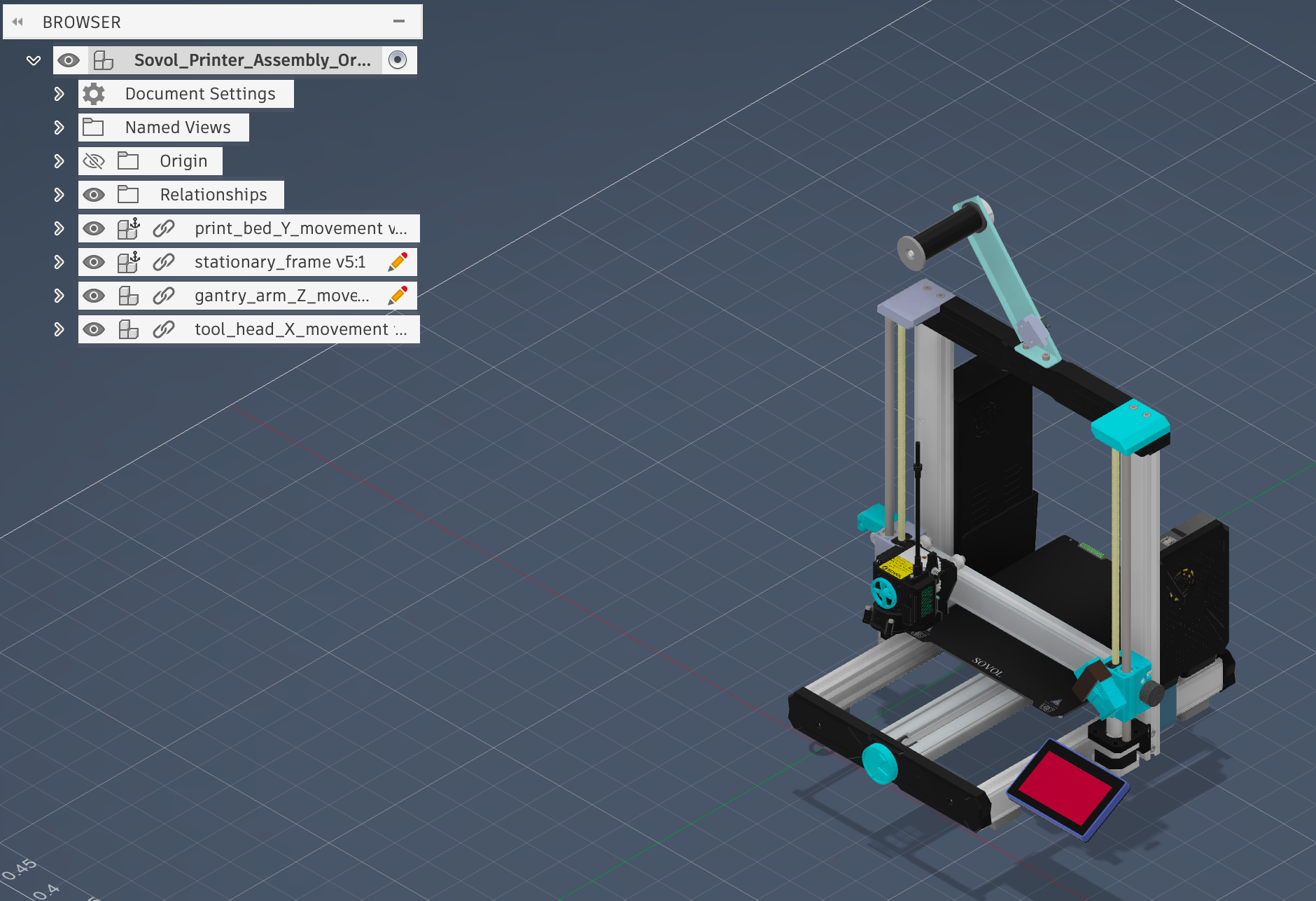
Two important steps I also took were setting the CAD file units to meters so it imported to Unity in the correct scale and positioning the printer at (0, 0, 0) so programming the digital twin in Unity would be easier (I did this by manually measuring and visually lining up CAD model with physical printer).
Once the digital model was done, next up was connecting the MTConnect software to the digital model so it could actually move and match the real printer. I did this using a development software for simulations and virtual reality experiences known as Unity. All of the code for this digital twin and the other work I did after is available in my Unity Github project. Since I did all of the work on my Mac laptop, it will likely need some adjustments to work on a Windows computer.
Building a working digital twin in Unity had a bit of a learning curve and took many steps to function correctly.
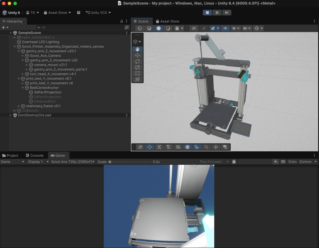
Pictured above is the part hierarchy of the Unity scene. The .fbx CAD file imports correctly, but the part parent/child relationship must be adjusted for it to move in the desired way. I set the toolhead as a child of the gantry arm so it moves up and down in sync. I also set a virtual camera as a child of the gantry arm for the same reason. To match the virtual camera view with the actual camera, I made several important changes (explained in April section).

To get the virtual model to move, I created several C# scripts. The file “move_testscript.cs” moves the model to a desired coordinate (x, y, z); “unity_mtconnect_reader.cs” parses the MTConnect XML data stream from the Raspberry Pi IP address for the position data and automatically moves the printer to that location with an adjustable settling time (video on next slide). The last script, “SpriteReceiver.cs” is for live object projection onto the print bed and will be explained in more detail in the next section of this page.
April – Digital Twin Live Demo, ROS Setup/URDF importer, Digital Twin Virtual Camera Matching, End Print Macro Update, SIFT Algorithm attempt, Live 3D Object Projection
April was the busiest month of this project by far. I took all of the work I had done up to that point and started actually trying to make something of it. The first was testing the Digital Twin and ensuring it moved accurately. See the short video below for a demonstration of the code while the printer is in use.
Although my work this semester focused mainly on the 3D printer, I did have some experience with the robotic manipulator arm. The arm can be fully simulated in Unity using existing software for ROS operation and the URDF importer package for Unity.
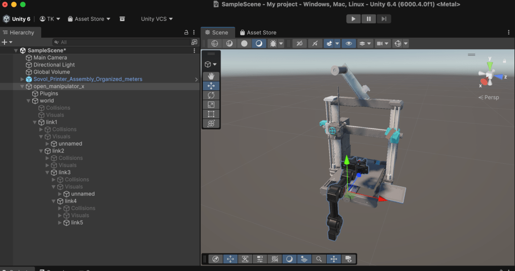
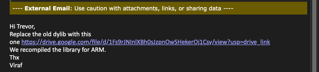
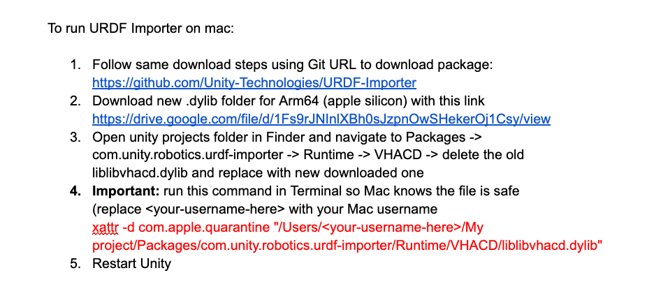
This software works great on Windows, but when I tried to import the file into my Unity scene on Mac, it had several compilation errors. This was because of how the newish Apple Silicon chips run Unity. To fix this error, I emailed the Unity robotics team and they thankfully sent an updated library file that fixed the issue! In the main project GitHub, the file “How to Run URDF Importer on Mac.pdf” details the instructions below for downloading the updated file and replacing the library (the library file is also included in the GitHub as “VHCD_universal_mac.zip” in case the Google Drive link stops working eventually).
As I mentioned earlier, I spent a while creating a virtual “match” of the real camera view. The original motivation for this came after deciding the PnP algorithm for part detection was not achievable and then looking into other methods. One that a Ph.D. student suggested was the SIFT algorithm (Scale Invariant Feature Transform, explained more later on this page). This algorithm identifies sharp edges to identify objects present in different photos.
In order to use the SIFT algorithm for this application I needed the virtual camera and real camera background views to closely match so the photos could be compared to track a part on the print bed. This proved to be quite a challenge. The method I eventually found that produces a close match began simply with placing a virtual camera in the same spot as the physical camera on the digital twin gantry. Next, I adjusted the camera settings to match the real lens size and FOV and changed the game window resolution to match the camera’s 640×480 live stream (Game resolution was actually set to 4 times larger at 2560×1920 to give a better experience for the user in Unity but has the same dimension scale).
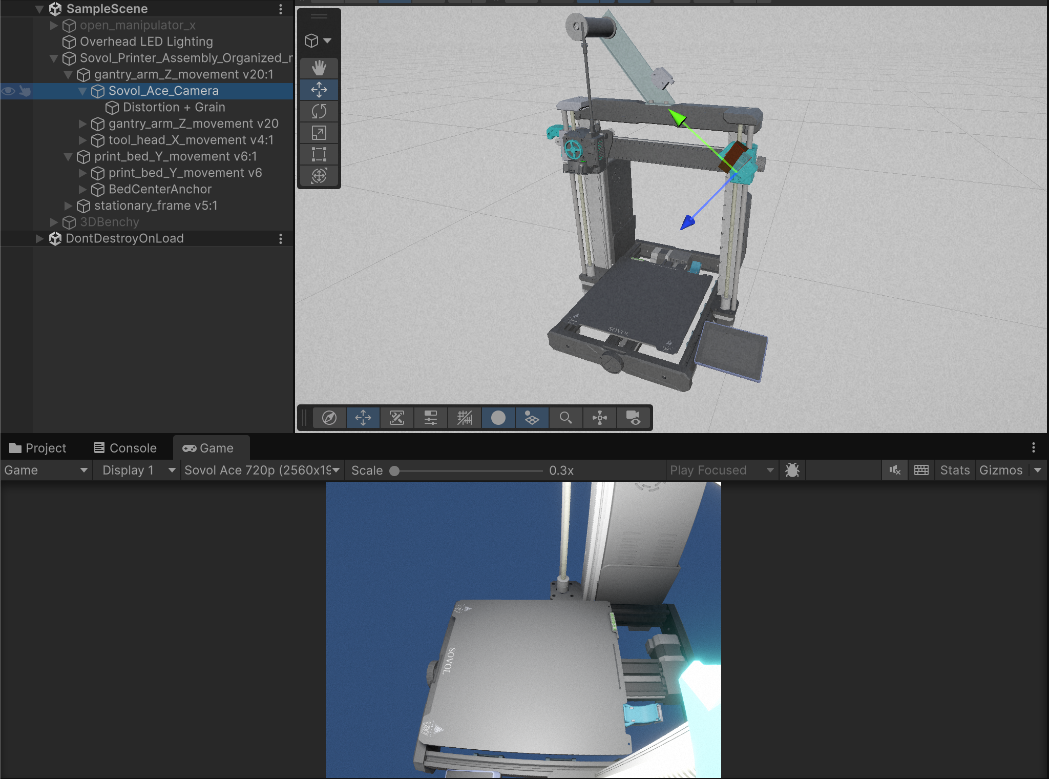
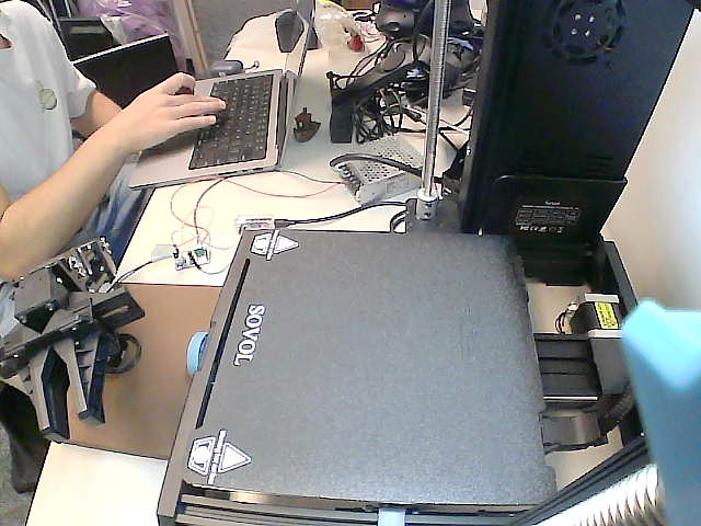
While this was close, there was still a missing aspect as the real image was bowed at the bottom. The printer uses a cheap low quality camera which distorts the image in interesting ways. To match this effect, I added a “global volume” in Unity that provides an adjustable lens distortion and film grain to match the image quality closer.
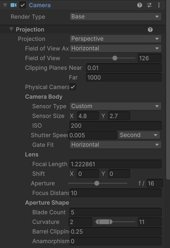
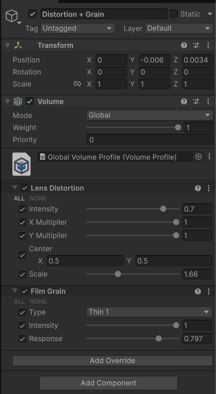
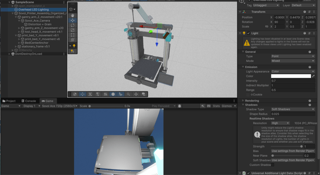
These camera settings and global volume gave an image that was pretty close, but there was still the issue of matching the lighting. Ultimately, what worked the best was adding a “point” lighting source in the same location as the LED lighting bar from Amazon that I attached to the physical printer. Through trial-and-error I adjusted the lighting intensity and range until it gave an acceptable image that is quite close to the actual camera view.
One problem I discovered was that after a print finishes, the toolhead moves to a low height “home” location and then disables the motors. This is not ideal for robotic arm retrieval, so I updated the printer macro code to fix this. Printer macro code is the programming that controls many of the basic actions of the 3D printing process such as bed heating, pre-print calibration, etc. In the main project GitHub the file END_PRINT_gcode_update.txt includes the exact code to copy paste into the printer macro settings. This can be done by typing in the printer IP address while connected to the same local network (e.g. 192.168.1.8), which brings up the Mainsail control page. On this page, go to the macro.cfg file and update the entire section labeled END_PRINT. This new code will position the printer near maximum height (1, 130, 250) so the print bed is fully in view of the camera and there is space for the robotic arm to retrieve the part. The video below demos this function.
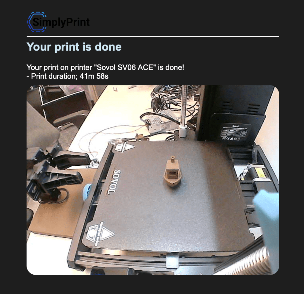
A cool feature with the SimplyPrint utility through OrcaSlicer is that it sends a photo of the print to your email after completion. By updating the end print macro, the photo is then taken from this elevated position. This combined with the low-angle mount gives a nice view.
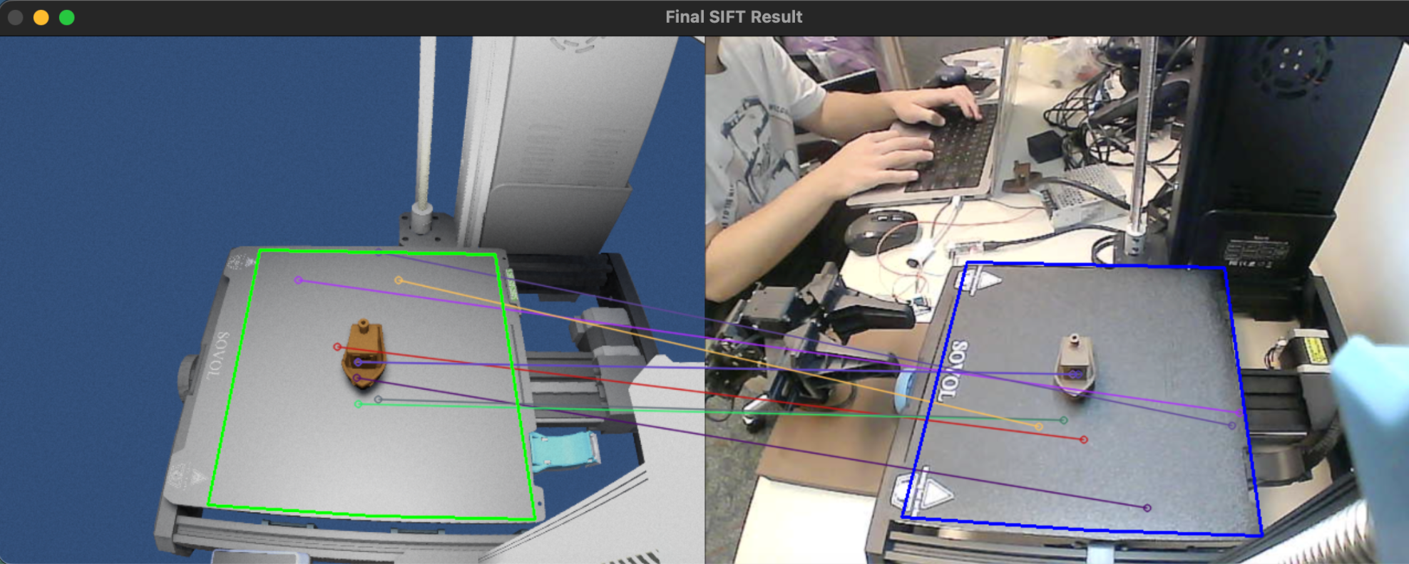
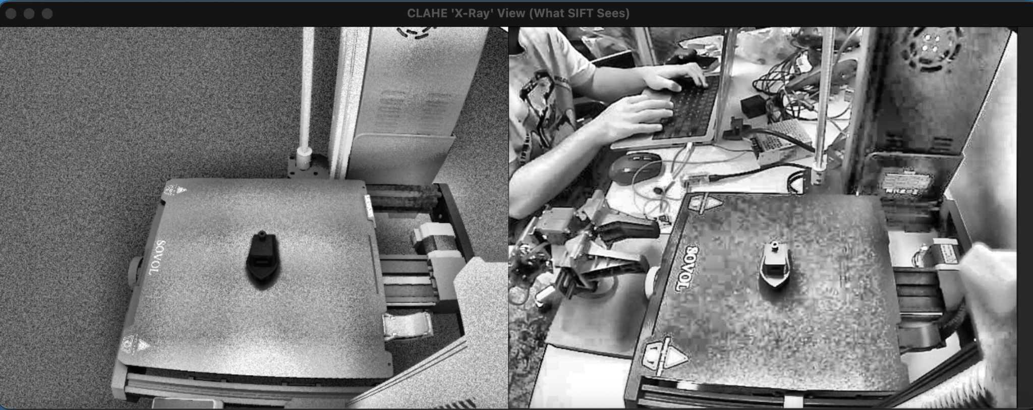
After finally getting the camera views matched up, I began working on implementing the SIFT algorithm to compare the virtual image with the live view to detect possible part or print defects like stringing. I spent several hours on the code but was unable to create a usable or effective program because of a few key issues. One is that the part in the virtual image needed to be in the correct location on the print bed, so this would need to be done manually based on the CAD file. This may have been doable, but the largest problem was that the virtual part reflects light differently than the real one. When the Python script amplified the contrast, the resulting image was bright for the real camera but dark virtually.
Unfortunately, this combined with the inherent variability in the actual image versus the simulation meant the image recognition was very inaccurate. I also came to the conclusion that it would be difficult to detect print errors as the printer was incredibly reliable for small parts like the Benchy (boat) model pictured below. Print errors would likely have to be manually induced which I felt somewhat defeats the purpose of the overall goal of robotic arm retrieval.
This train of thought led me to wonder if the part on the print bed could be tracked and then digitally simulated into the virtual model (subtle foreshadowing).
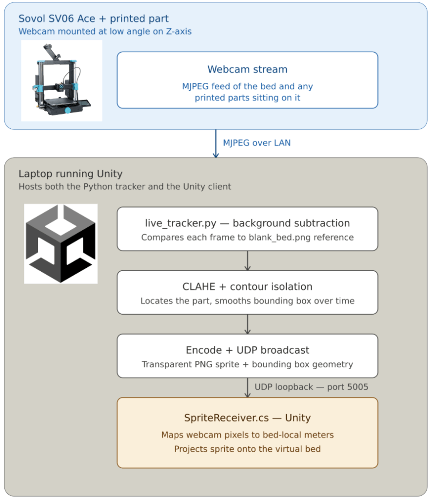
For my last bit of work, I created what ended up being a pretty intriguing way to model printed objects in a virtual environment. It uses a couple interesting techniques to project a 2D image of a printed part from the live camera web stream into a 3D object on the digital twin print bed. I created a blank 3D part and placed it on the center of the print bed and set it as a child so it moves wherever the print bed does. The Python script compares the live image to a blank bed photo to identify an object, then captures the part outline with several image “cleaning” techniques. The image outline is then sent over a UDP socket connection and the receiving Unity script uses that image as an object texture. The texture is displayed on the top side of the blank object. By manually setting a mask on the real camera image bed and finding the pixel size of the virtual bed, I was able to get a conversion factor between the two. This means that the projected image is nearly the exact correct size and in the correct place on the print bed. For object height, I currently just have that manually set based on the known height of the Benchy part print.
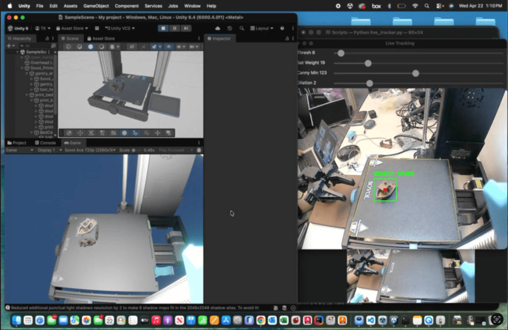
My idea for implementing this with the robot arm in the future is to use the last known toolhead height before it executes the end print macro. The script in Unity can then set this as the projected object height. The robot arm can use the live part position data to move near the part and then a closing detection algorithm to grab it with its grippers.
Here is a diagram outlining how this process functions, much more specific detail can be found in the main project GitHub readme file.
I liked this part of the project the most as it tied in nearly all of my work throughout the semester (Printer API, Camera mount, Digital Twin CAD, Computer Vision). This code could definitely be updated to run on a Raspberry Pi instead of a laptop, but I thought it was nice to have a live updating window showing the part detection.
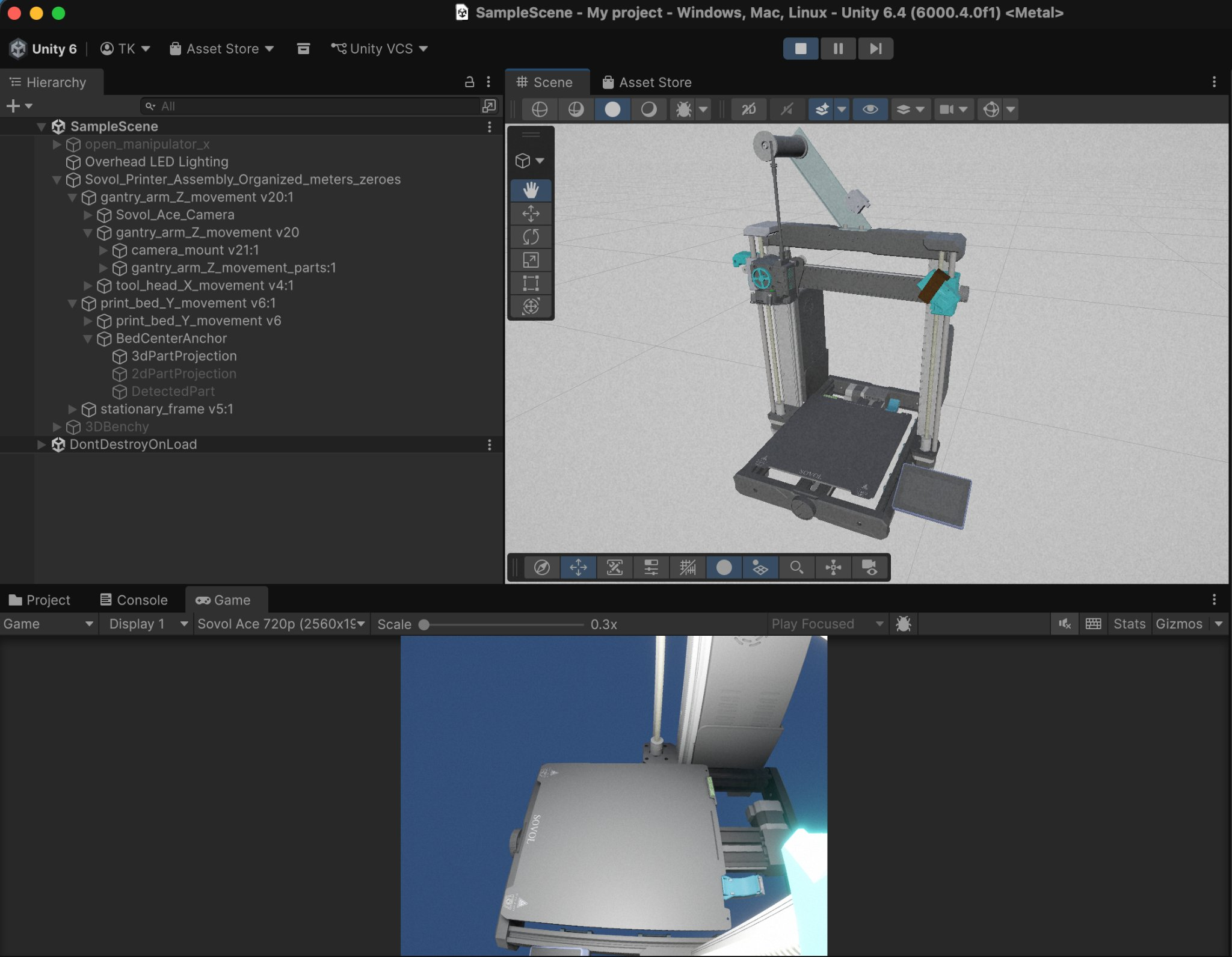
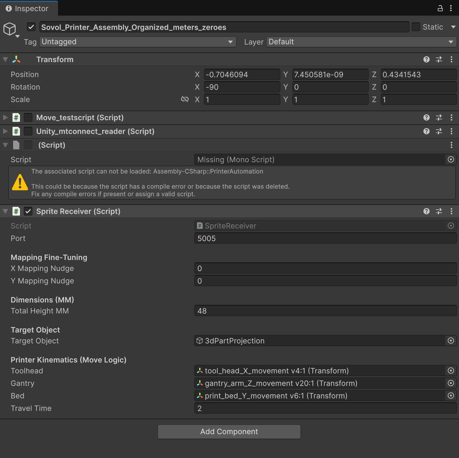
Above are some of the script settings, and the objects near the bottom allow the script to move the desired parts and then project the detected texture onto the blank object. This next video is a short demo of the object projection followed by a longer testing clip that shows more of the setup and run process.
Semester Reflection/Takeaways
This project was a great chance to explore a ton of new topics and learn a lot of information I would not have otherwise. I greatly improved my Python and C# coding skills, computer vision knowledge, and got much better at designing and printing parts with a 3D printer. AI tools (mainly Gemini Pro free student trial, some Claude) were an invaluable resource for troubleshooting and assisting with writing code for this project, while I also manually debugged and designed most of the logic. I think my work is a strong base for a lot of content for the future class, but there is still work to do in order to integrate the manipulator arm to actually grab and retrieve the part. In my opinion, the class would be best as a way to showcase and learn how the code works rather than having students recreate it on their own. This is because of the incredible amount of time it took to troubleshoot through the seemingly infinite number of issues that can arise when making something like this. Perhaps once the robotic arm code is integrated, students could focus on creating parts and programming that aspect rather than trying to add to the 3D printer code and backend side.
Now, grad class development aside, is this research inherently useful and was it a good use of time? Well no and maybe. The actual content isn’t all that important or groundbreaking for this industry and doesn’t really help anyone with their daily lives. That being said, I think the final product, if nothing else, was kinda cool and I definitely learned a lot. And really the most impactful and valuable inventions often come by accident or while trying to solve unrelated problems, so this was worth doing even if it ended up being not all that significant.
